
Map display method and device for LED lamp on virtual display terminal

A map display device, LED light technology, applied in geographic information databases, special data processing applications, instruments, etc., can solve problems such as difficulty in individual identification, optimize user experience, optimize fault feedback efficiency, and avoid list page switching.

Inactive Publication Date: 2014-10-08
GUANGDONG KAILESI OPTOELECTRONICS SCI & TECH
View PDF2 Cites 4 Cited by
  • Summary
  • Abstract
  • Description
  • Claims
  • Application Information

AI Technical Summary

Problems solved by technology

[0004] The purpose of the present invention is to overcome the shortcomings and deficiencies of the prior art, and provide a map display method for LED lamps on a virtual display terminal. For problems such as individual identification difficulties, combined with distance positioning technology, a convenient function of directly locating and addressing LED lights through maps is provided, so that users can accurately position and control LED lights in actual corresponding geographic locations through the marks on the map

Method used


Image

  • Map display method and device for LED lamp on virtual display terminal
  • Map display method and device for LED lamp on virtual display terminal
  • Map display method and device for LED lamp on virtual display terminal

Examples


Embodiment 1

[0045] The technical scheme that this method invention solves its technical problem adopts is:

[0046]Assume that the stair room floor plan and LED light information are stored in the database in advance, where the LED light information includes status, type, and coordinate position information, where the status includes on, off, and fault, etc., and the types include floor lamps and strip lights, etc., The coordinate position information can be in the form of (X-axis, Y-axis), or in the form of (male radius, radian).

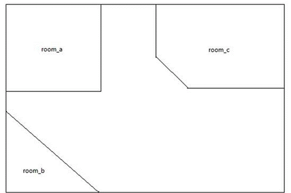
[0047] 1. Check the room layout and obtain the floor plan of the stair room from the database, as attached figure 1 shown. Obtaining the floor plan of the stair room is first to obtain the file name of the floor plan in the database, and then download the floor plan of the stair room corresponding to the file name from a font library in the database—picture library.

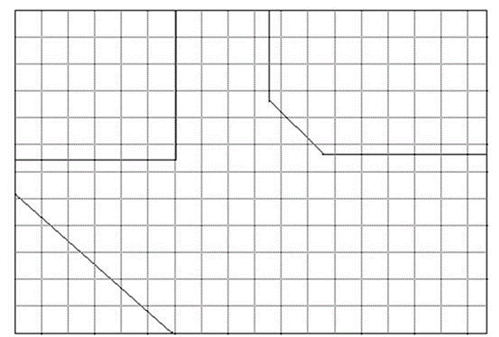
[0048] 2. Divide the grid on the floor room layout map in advance, and each room is regarde...

Embodiment 2

[0056] Assuming that the display area of ​​the room floor plan is 600x400px, the LED light information obtained from the database through the server is as follows:

[0057] LED_A type: floor lamp, online, coordinate information: x=229, y=149;

[0058] LED_B type: bar light, fault, coordinate information: x=341, y=237;

[0059] Create a grid div with the same size as the room plan. The file name of the grid is paint_div, and the position is set to relative so that the grid div overlaps with the room plan. The z-index is above the room plan, where position , relative, absolute, etc. are based on some style attributes and values ​​​​of HTML, and are limited to Web-based representation methods.

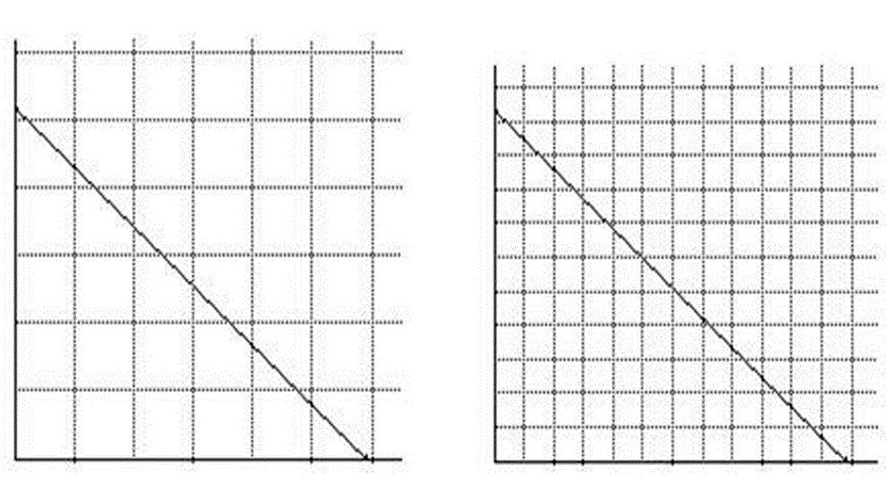
[0060] The actual size of the display area needs to be 300 x 200px (zoomed by 50%). First, the room floor plan is scaled and displayed according to the display area, and a virtual drawing layer with the same size as the display area is created to overlap the room floor plan. Draw on the...


PUM


Abstract

The invention relates to a map display method and device for an LED lamp on a virtual display terminal. The method comprises the steps that a stair room plane layout is obtained, mesh generation is conducted on the stair room plane layout, a coordinate reference system of a room building skeleton map is established, the coordinate positions of all LED lamps are converted and quantized, and the LED lamps are drawn. The map display method and device solve the problems that of the geographical limitation and functional limitation of control over existing LED lamp products in the prior art, and the difficult identification of individuals on cluster control occasions, a distance locating technology is combined, the convenient function that direct locating and addressing are conducted on the LED lamps through a map, and a user can accurately locate and control the LED lamps at actual corresponding geological positions through the identification on the map. Under the map presentation mode, the user can more visually mark and feed back the contrast relations of real physical individuals and marks on the map, and the target unit needing to be controlled can be rapidly and conveniently addressed simply according to a physical reference and the marks on the map.

Description

technical field [0001] The invention relates to the technical field of LED lamp cluster control, in particular to a method and device for displaying a map of LED lamps on a virtual display terminal. Background technique [0002] With the popularization of the concept of the Internet of Things, consumers' requirements for the experience index of the living environment continue to increase, which has attracted the attention of emerging industries such as smart home, and due to the maturity of today's software technology and hardware technology, it has gradually moved from concept to reality. Smart home brings consumers a better device interaction experience, but judging from the smart home industry currently on the market, it is not difficult to see that the consumer targets of this type of industrial products are concentrated in small families, and the homes managed by individual users The small number of products cannot cope with the application environment of enterprise ap...

Claims


Application Information

Patent Timeline
Patent Type & Authority Applications(China)
IPC IPC(8): G06F17/30
CPCG06F16/29
Inventor 伍永乐余从刚蔡嘉敏
Owner GUANGDONG KAILESI OPTOELECTRONICS SCI & TECH
Learn More