PS-DInSAR ground surface deformation measurement parameter estimation method based on optimal solution space search method

A technology of spatial search and surface deformation, applied in the field of radar, which can solve the problems of limiting algorithm efficiency, estimation error, and no parameter estimation method yet.

Active Publication Date: 2014-10-08
BEIHANG UNIV
View PDF4 Cites 40 Cited by
  • Summary
  • Abstract
  • Description
  • Claims
  • Application Information

AI Technical Summary

Problems solved by technology

[0003] The two-dimensional periodogram method is a commonly used PS-DInSAR parameter estimation method, which regards the differential phase as the T-B space (time baseline-space baseline space) to The two-dimensional Fourier transform value of the space, using the method of spectrum estimation to estimate Δv and In the case of uneven distribution of time and space baselines and a small number of SAR images, the two-dimensional periodogram method often cannot obtain reasonable estimation results, and the estimation error is large
In the absence of prior knowledge, in order to improve the accuracy of parameter estimation, it is often necessary to use a larger range of solution space and a smaller search step size, which limits the improvement of algorithm efficiency; in addition, the point with the largest phase coherence coefficient in the solution space Often not necessarily Δv and The true value of , there is a large estimation error
[0005] In summary, there is no high-precision and high-efficiency parameter estimation method for PS-DInSAR surface deformation measurement

Method used


Image

  • PS-DInSAR ground surface deformation measurement parameter estimation method based on optimal solution space search method
  • PS-DInSAR ground surface deformation measurement parameter estimation method based on optimal solution space search method
  • PS-DInSAR ground surface deformation measurement parameter estimation method based on optimal solution space search method

Examples


Embodiment

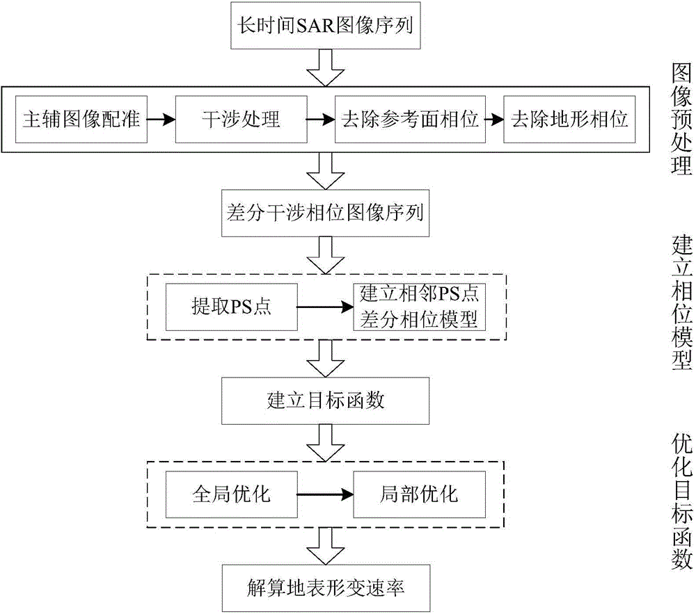
[0080] The present invention is a PS-DInSAR surface deformation measurement parameter estimation method based on an optimized solution space search method, and the specific embodiments are as follows:

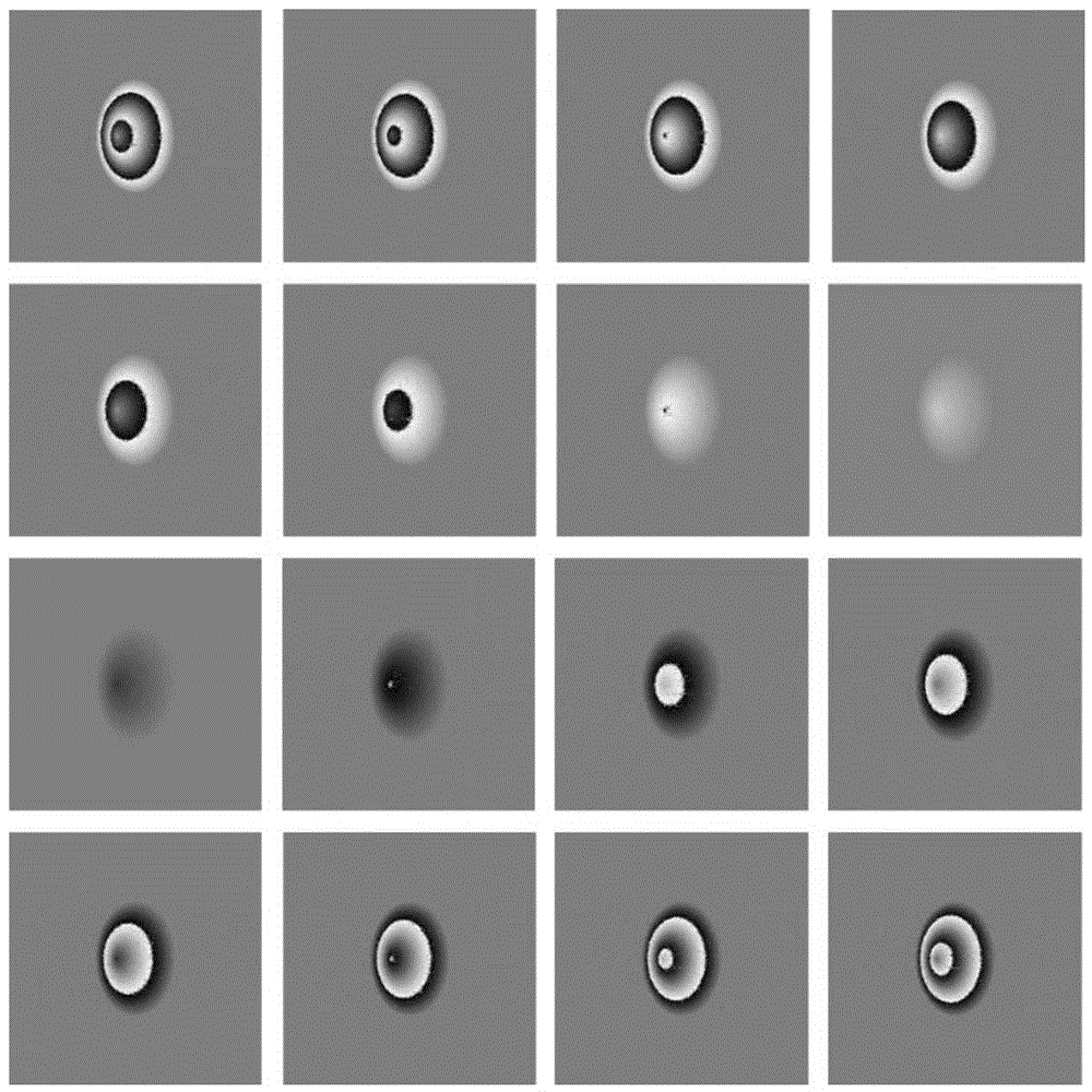
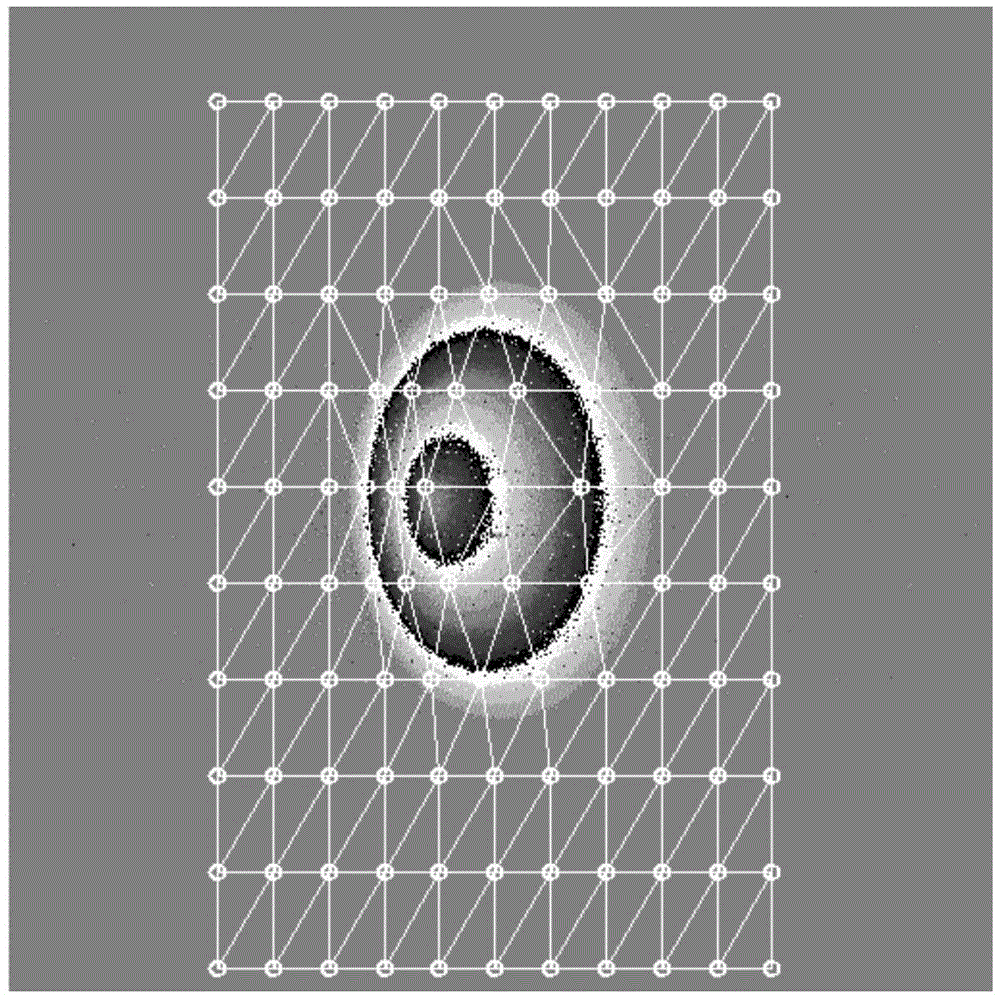
[0081] Step 1: Generate K+1=17 SAR images by simulation. In the center of the scene in the SAR image, there is a conical mountain peak with a diameter of 700m. Its height increases at a rate of 0.01m per year. The SAR image sequence is generated at a sampling interval of 0.5 years, and the SAR image of the 4.5th year is selected as the main image, at this time the peak height is 120m, and the rest of the images are used as auxiliary images. Register each auxiliary image with the main image, and perform interference calculation, remove the reference plane phase and terrain phase, and obtain K differential interferometric phase images, such as figure 2 shown. In the scene corresponding to the SAR image, 110 scattering points with large backscattering coefficients are arranged ...


PUM


Abstract

The invention discloses a PS-DInSAR ground surface deformation measurement parameter estimation method based on an optimal solution space search method. The method comprises the first step of obtaining a difference interferometric phase image sequence, the second step of extracting permanent scatterer points from the difference interferometric phase image sequence and constructing a Delaunay triangular network, the third step of calculating the second-order difference phases of each pair of adjacent PS points in a kth difference interferometric phase image, the fourth step of establishing an objective function to be optimized, the fifth step of searching for the objective function in a two-dimensional solution space, the sixth step of conducting local optimization on the objective function through the Levenberg-Marquardt algorithm, and the seventh step of solving the ground surface deformation quantity and an elevation error. According to the PS-DInSAR ground surface deformation measurement parameter estimation method based on the optimal solution space search method, signal sampling is not involved, so that the influence of all interference images on nonuniformity of time and space base lines is avoided, a high-precision result can still be obtained without priori knowledge, and a new thought and path are provided for ground surface deformation measurement.

Description

technical field [0001] The invention relates to the field of radar technology, in particular to a surface deformation measurement method based on a permanent scatterer synthetic aperture radar differential interferometry technique based on an optimized solution space search method. Background technique [0002] Permanent Scatterer Synthetic Aperture Radar Differential Interferometry (PS-DInSAR) is a method that uses the phase information of permanent scatterers (PS) with stable surface scattering characteristics to establish a reasonable differential phase model of adjacent PS points, and obtains the surface deformation, Measurement techniques for elevation errors, etc. However, due to factors such as atmospheric delay, nonlinear deformation, and phase winding, it is extremely difficult to solve the model, and it is often necessary to reasonably estimate the difference Δv in the deformation rate of adjacent PS points in the model and the difference in elevation error and o...

Claims


Application Information

Patent Timeline
Patent Type & Authority Applications(China)
IPC IPC(8): G06F19/00G01S13/90
Inventor 徐华平王碧君
Owner BEIHANG UNIV
Why Eureka
Try Eureka