
Incandescent lamp

An incandescent lamp and lamp cap technology, applied in the field of incandescent lamps, can solve the problems of inability to guarantee the effect, deviation of the filament from the correct position, short service life of the incandescent lamp, etc., and achieve the effect of avoiding premature wire breakage

Inactive Publication Date: 2014-10-08
KUNSHAN BOWEN LIGHTING TECH
View PDF3 Cites 0 Cited by
  • Summary
  • Abstract
  • Description
  • Claims
  • Application Information

AI Technical Summary

Problems solved by technology

However, this does not guarantee the desired effect
This is because the filament is also severely misaligned from its correct position relative to the outer reflector due to the fact that the incandescent lamp is generally firmly fixed to the lamp socket
In addition, when using Swan lamp caps and lamp holders, if the position of the lamp holder relative to the reflector is not correct, such deviations will also occur
It was also found that known incandescent lamps had a short service life

Method used


Image

  • Incandescent lamp
  • Incandescent lamp

Examples


Embodiment Construction

[0015] The present invention will be further described below in conjunction with the accompanying drawings.

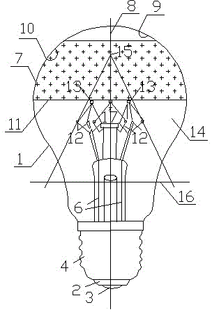
[0016] figure 1 The incandescent lamp has a vacuum-sealed glass bulb 1. The bulb 1 is equipped with a lamp cap 2 with contacts 3 and 4. The bulb 1 is equipped with a filament 5, which is connected to the contacts 3 and 4 of the lamp cap 2 through a current supply conductor 6. 2 Opposite the bulb there is a hemispherical part 7 which has an axis of symmetry 8 and a mirror coating 10 , with the exception of parts close to and around the axis 8 which do not have a mirror coating. In the illustrated incandescent lamp the bulb 1 is transparent with the exception of the mirror coating 10. In the embodiment shown the mirror coating 10 is an internal coating deposited by aluminum vapor, and it is advantageous that the bulb be transparent because it allows the light to The filament 5 is arranged on several support points 12, 13 around the axis of symmetry 8 near the widest in...


PUM


Abstract

The invention discloses an incandescent lamp. A hemispherical part (7) of a bulb (1) is provided with an environment coating (10), and a lamp filament (5) of the incandescent lamp is arranged between supporting points (12 and 13) located on the surface of an assumed cone (14) and is located outside the bulb mirror surface coating (10). The incandescent lamp is especially suitable for being used as a traffic signal lamp, the incandescent lamp is used in cooperation with an external reflector of the paraboloid to generate high-light-intensity light beams in the center of the light beams and in the direction surrounding the axis of the light beams by a small angle, and therefore the power consumption of the incandescent lamp can be very small.

Description

technical field [0001] The invention relates to an incandescent lamp. This incandescent lamp has a vacuum-sealed glass bulb. The bulb is attached with a cap with contacts. The part is basically hemispherical. This part has an axis of symmetry and a reflective coating, but there is no reflective coating except for the parts near and around the axis of symmetry. The filament is arranged around the axis of symmetry near the widest interface of the reflective coating. between support points. technical background [0002] Known incandescent lamps have a filament arranged in a plane perpendicular to the axis of symmetry, in the hemispherical part of the bulb. [0003] The incandescent lamps mentioned at the outset of the description are used, for example, in parabolic external reflectors. The light from the filament striking the reflective coating of the bulb is reflected onto the outer reflector and is concentrated by the outer reflector together with the light from the filamen...

Claims


Application Information

Patent Timeline
IPC IPC(8): H01K1/18H01K1/32
Inventor 熊开富
Owner KUNSHAN BOWEN LIGHTING TECH
Learn More