Liquid cooling rack of miniature array device

A liquid-cooled rack and equipment technology, applied in the direction of cooling/ventilation/heating transformation, etc., can solve problems such as effective thermal management and maintainability, performance degradation or shutdown, and poor heat dissipation of high heat flow equipment at the same time, so as to shorten field maintenance Time, good heat dissipation, and good temperature consistency

Active Publication Date: 2014-10-08
SOUTHWEST CHINA RES INST OF ELECTRONICS EQUIP
View PDF6 Cites 12 Cited by
  • Summary
  • Abstract
  • Description
  • Claims
  • Application Information

AI Technical Summary

Problems solved by technology

However, only the transceiver module can effectively dissipate heat, while the power module and digital processing module often have poor heat dissipation and performance degradation or shutdown; when replacing the transceiver module, the device needs to be completely disassembled, and there is a thermal adjustment after the liquid cooling rack is disassembled. link, resulting in poor maintainability
[0004] Neither of these two solutions can simultaneously solve the problems of high heat flux dissipation, effective thermal management of equipment, and maintainability under the constraints of limited liquid cooling resources and miniaturization

Method used


Image

  • Liquid cooling rack of miniature array device
  • Liquid cooling rack of miniature array device
  • Liquid cooling rack of miniature array device

Examples


Embodiment Construction

[0028] Describe the present invention below in conjunction with specific embodiment:

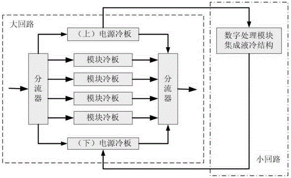
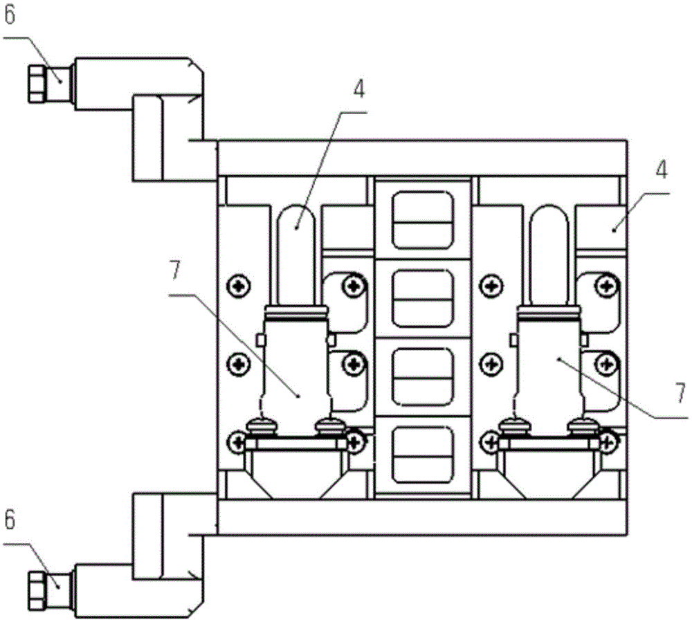
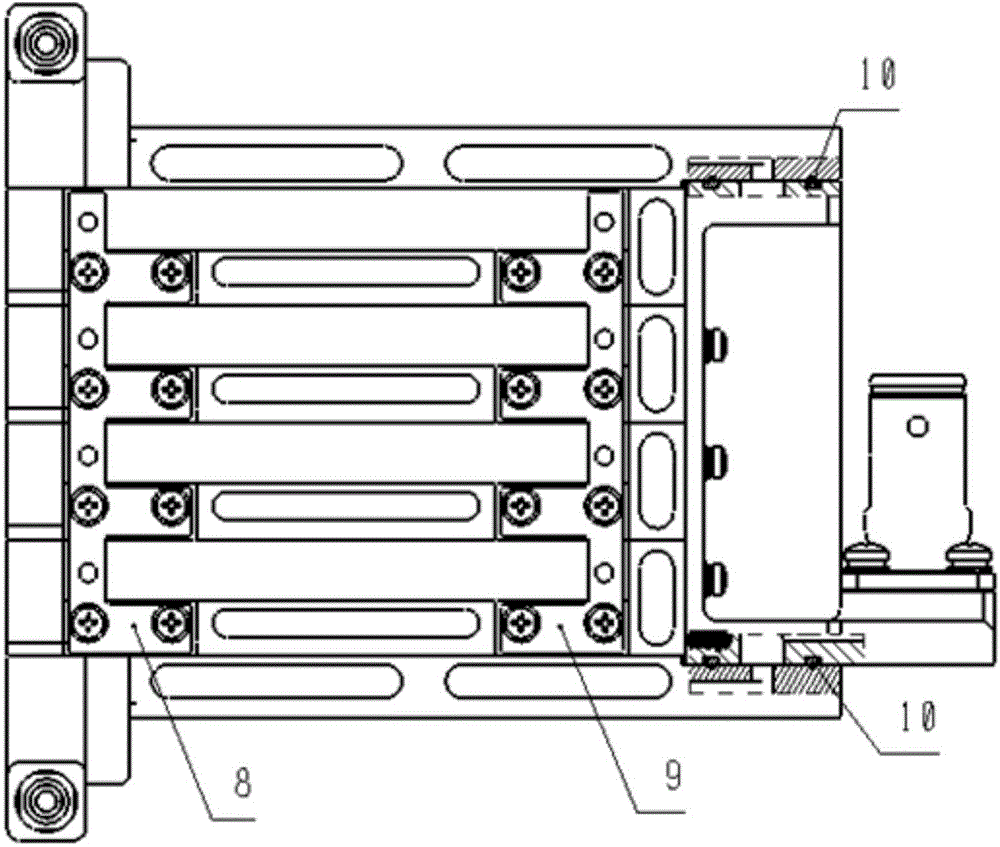
[0029] Refer to attached figure 2 ~ attached Figure 5 , the liquid-cooled rack of the miniaturized array equipment in this embodiment consists of four module cold plates, two power supply cold plates, two shunts, eight blind-mating liquid connectors, and two self-sealing blind-mating liquid connectors , two self-sealing bayonet liquid connectors and a guide frame.

[0030] The splitter is connected to the external coolant source through a self-sealing bayonet liquid connector, the front side splitter is used as the coolant inlet, and the rear side splitter is used as the coolant outlet; on the main channel of the splitter, there is a split cooling to the module cold plate and the power supply cold plate liquid flow channel. Taking the two splitters as the assembly reference, the cold plate of each module is connected horizontally to the two splitters simultaneously through two blind-mat...


PUM


Abstract

The invention provides a liquid cooling rack of a miniature array device. Flow dividers are connected with an external cooling liquid source through self-sealing bayonet liquid connectors. Main flow channels of the flow dividers are provided with branch flow channels for dividing cooling liquid to module cold plates and power cold plates. The module cold plates are communicated with the flow dividers through blind insertion liquid connectors. A mounting space for a receiving and dispatching module is formed between the adjacent module cold plates. The two power cold plates are fixedly arranged above and below the integration of the module cold plates respectively. The power cold plates are connected with a digital processing module integrated liquid cooling structure through self-sealing blind insertion liquid connectors. The liquid cooling rack has the functions of complex flow channel organization, heat dissipation and force bearing; through a compact and ingenious structural layout and flow channel design, heat dissipation of the receiving and dispatching module with high heating flux density is achieved through limited liquid cooling resources; meanwhile, effective heat management of multiple functional modules with differentiated heat dissipation requirements is achieved, and the miniaturization requirement for platform loading is met.

Description

technical field [0001] The invention relates to the technical field of thermal management and structural design of avionics equipment, and specifically relates to a liquid-cooled rack for miniaturized array equipment. Background technique [0002] The RF front-end equipment of an active phased array system (hereinafter referred to as equipment) usually consists of a transceiver module, a digital processing module, a power supply module, other functional modules and a liquid-cooled rack. The continuous improvement of equipment performance has led to the continuous increase of device heat flux density and total heat dissipation power of equipment, thus putting forward higher requirements for heat dissipation capability, and the miniaturization requirements of military aviation platforms for equipment have exacerbated the difficulty of heat dissipation for equipment. [0003] There are two solutions based on current structural technology. First, the customized drawer-type liqu...

Claims


Application Information

Patent Timeline
Patent Type & Authority Applications(China)
IPC IPC(8): H05K7/20
Inventor 任川王超
Owner SOUTHWEST CHINA RES INST OF ELECTRONICS EQUIP
Why Eureka
Try Eureka