Refraction-reflection optical fingerprint sensor structure

A fingerprint sensor, catadioptric technology, applied in the direction of instruments, character and pattern recognition, computer parts, etc., can solve the problem that the optical fingerprint sensor cannot accurately control the adjustment of focal length and fixed focal length, increase the volume of the optical fingerprint sensor, and cannot be used Demand and other issues, to achieve the effect of miniaturization, convenient production and manufacturing, and reduce the difficulty of focusing

Inactive Publication Date: 2015-11-11
HANGZHOU ZHIAN TECH
View PDF5 Cites 5 Cited by
  • Summary
  • Abstract
  • Description
  • Claims
  • Application Information

AI Technical Summary

Problems solved by technology

As optical fingerprint sensors have been used more and more in product fields such as fingerprint door locks, fingerprint access control, fingerprint cabinets, and even smart phones, people are increasingly pursuing the miniaturization and easy production of optical fingerprint sensors (mass production) Rapid production and testing and guarantee of consistency), while the traditional optical fingerprint sensor internally arranges prisms, lenses, diaphragms and imaging devices along the direction of the optical axis, using the principle of straight-through optical axis design, which results in The axial distance of the optical fingerprint sensor is longer or shorter. When the axial distance is longer, the volume of the optical fingerprint sensor is increased, which is not conducive to the pursuit of miniaturization and easy production requirements; The fingerprint sensor will not be able to accurately control the focal length adjustment and fixed focal length, which greatly increases the difficulty of focusing, and is not conducive to manufacturing and use, reduces production efficiency, and is not conducive to the pursuit of miniaturization and easy production requirements; the traditional reflective Optical fingerprint sensors are usually unable to suppress stray light, because part of the scattered light emitted by the light source will also directly reach the imaging device through total reflection or the natural light incident on the acquisition window will enter the acquisition device through transmission, which will interfere with the final imaging. The image is not clear and cannot meet people's needs

Method used


Image

  • Refraction-reflection optical fingerprint sensor structure
  • Refraction-reflection optical fingerprint sensor structure

Examples


Embodiment Construction

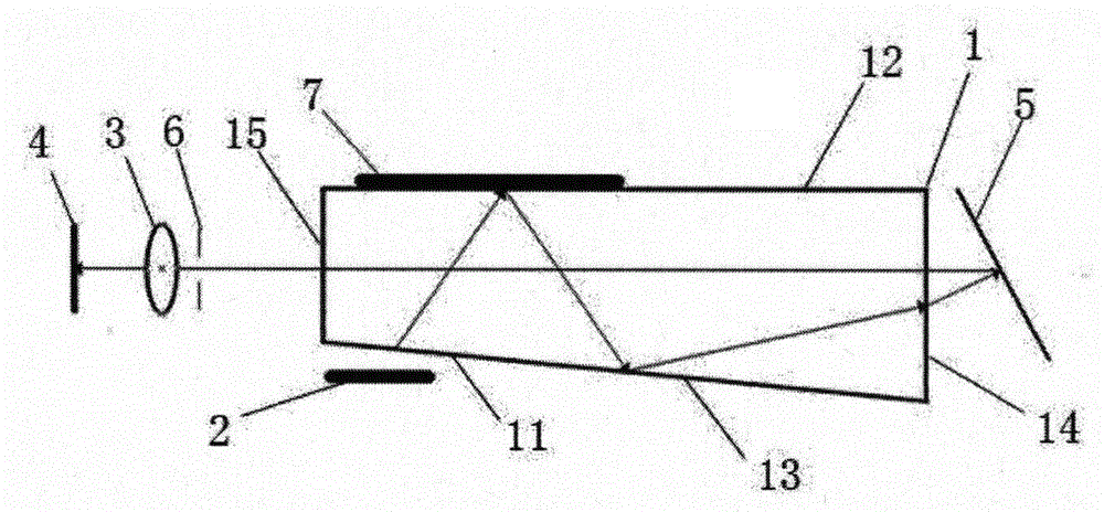
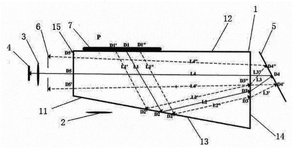
[0013] Such as figure 1 As shown, a catadioptric optical fingerprint sensor structure includes a collection prism 1, a light source 2, a lens 3 and an imaging device 4, and the collection prism 1, light source 2, lens 3 and imaging device 4 are installed in a housing; The collection prism 1 at least includes an incident surface 11, a collection surface 12, a total reflection surface 13, an exit surface one 14 and an exit surface two 15, the incident surface 11 and the total reflection surface 13 are in the same plane, and the exit surface one 14 is parallel with exit surface two 15, and exit surface one 14 has angle one with total reflection surface 13; The exit surface one 14 outer surface of described collection prism 1 is correspondingly provided with a reflector 5, exit surface one 14 and reflector 5 There is an included angle 2 between them, and the outer surface of the exit surface 15 of the collecting prism 1 is correspondingly provided with an imaging device 4, and an ...


PUM


Abstract

The invention discloses a refraction-reflection optical fingerprint sensor structure comprising an acquisition prism, a light source, a lens, and an imaging device which are all installed in a housing. The acquisition prism at least comprises an incident surface, an acquisition surface, a total reflection surface, an exit surface 1 and an exit surface 2. The incident surface and the total reflection surface are arranged in the same plane. The exit surface 1 and an exit surface 2 are arranged in parallel. An intersection angle 1 is arranged between the exit surface 1 and the total reflection surface. A reflector is correspondingly disposed on the outer surface of the exit surface 1 of the acquisition surface. An intersection angle 2 is arranged between the exit surface 1 and the reflector. The imaging device is correspondingly disposed on the outer surface of the exit surface 2 of the acquisition surface. A diaphragm is installed between the imaging device and the exit surface 2. An intersection angle 3 is arranged between the exit surface 2 and the imaging device. Optical path reflection and refraction are achieved on the acquisition prism such that the length and focal depth of an optical axis are effectively increased. Therefore, high manufacture precision is achieved and product requirements for easy manufacturability and miniaturization are achieved.

Description

technical field [0001] The invention relates to the technical field of fingerprint sensors, in particular to a catadioptric optical fingerprint sensor structure. Background technique [0002] Fingerprint sensor (also known as fingerprint sensor) is the key device to realize the automatic collection of fingerprints. At present, fingerprint sensors are mainly divided into two types, optical fingerprint sensors and semiconductor fingerprint sensors. Among them, optical fingerprint sensors are more widely used in the market, and optical fingerprint sensors are mainly Using the principle of refraction and reflection of light, put your finger on the optical lens, and the finger is illuminated by the built-in light source. The light shoots from the bottom to the prism or polygon mirror, and then shoots out through the prism. The light emitted is on the uneven lines of the finger surface fingerprint The angle of refraction and the light and shade of the reflected light will be diffe...

Claims


Application Information

Patent Timeline
Patent Type & Authority Applications(China)
IPC IPC(8): G06K9/00
CPCG06V40/1324
Inventor 巩少斌裴育敖玉华林日铢
Owner HANGZHOU ZHIAN TECH
Why Eureka
Try Eureka