Airbag-type rapid pressure increase or decrease control system in elevator car

A technology of elevator car and control system, which is applied to elevators, lifts, transportation and packaging in buildings, etc., can solve the problems of long transition time, no specific description, and insufficient air pressure changes, and achieves increased air pressure, The effect of reducing air pressure

A technology of elevator car and control system, which is applied to elevators, lifts, transportation and packaging in buildings, etc., can solve the problems of long transition time, no specific description, and insufficient air pressure changes, and achieves increased air pressure, The effect of reducing air pressure

CN104098002AInactive Publication Date: 2014-10-15TONGJI UNIV

Image

  • Airbag-type rapid pressure increase or decrease control system in elevator car
  • Airbag-type rapid pressure increase or decrease control system in elevator car
  • Airbag-type rapid pressure increase or decrease control system in elevator car

Examples


Embodiment 1

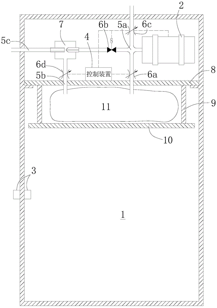
[0052] image 3 It shows the structure diagram of the air pressure control system in the elevator car involved in the present invention, which is used to control the air pressure in the elevator car 1 . The air pressure control system in the elevator car is set on the top of the elevator car 1. The system has: a nearly airtight elevator car 1 with only a small amount of air leakage during the up and down running of the elevator. Moreover, the elevator car 1 is in the During the operation, it only stops at two places, the ground floor and the top floor, and does not stop at the middle floor; a gas generator 2 is arranged on the top of the elevator car 1, and the gas generator can quickly generate a large amount of gas in a short time. Gas is generated by a blower or an air compressor, or by a chemical reaction; the piping group 5 has a right end connected to the gas generator 2, a lower end connected to the air bag 11, and a left end connected to the vacuum generator 7 Air inl...

Embodiment 2

[0064] Figure 4 It shows the structural diagram of the air pressure control system in the elevator car according to the present invention, and controls the air pressure in the elevator car 1 . The air pressure control system in the elevator car includes: a nearly airtight elevator car 1, there is only a small amount of air leakage during the up and down running of the elevator, and the elevator car 1 is only between the ground floor and the top floor during operation Stop everywhere, not intermediate floors. Furthermore, the elevator car 1 has an additional volume chamber 13 . The volume chamber 13 is divided into an upper volume chamber 13a and a lower volume chamber 13b by a piston 12 closely matched with the wall surface of the volume chamber. The device 2 is connected through the connecting pipe 5g of the lower volume chamber. The air between the upper and lower volume chambers is isolated by the piston 12 and cannot communicate with each other. There is also a stopper ...


PUM


Abstract

The invention relates to an airbag-type rapid pressure increase or decrease control system in an elevator car. The airbag-type rapid pressure increase or decrease control system is used for controlling the air pressure in a car of a nearly-closed elevator, and is characterized by comprising a gas generator, a tubing group, a valve group, an airbag, an air pressure detection device and a control device, wherein the pressure of air in the elevator car is controlled to be rapidly decreased or increased during an ascending or descending process of the elevator by virtue of rapidly inflating or deflating the airbag, so that the air pressure in the elevator car is controlled. Compared with the prior art, the airbag-type rapid pressure increase or decrease control system is capable of rapidly increasing or decreasing the pressure of the elevator car, thus improving the discomfort caused by ear pressurization of passengers in the ultra high-speed elevator car during the ascending or descending process.

Description

technical field [0001] The invention relates to an air pressure control system, in particular to an air bag type rapid increase and decrease control system in an elevator car. Background technique [0002] In recent years, super high-rise buildings have sprung up in various countries. Correspondingly, ultra-high-speed elevators, as an essential facility in super high-rise buildings, are also developing towards faster speeds and longer journeys. But in the process of faster and higher development, it will inevitably bring about a problem, that is, as the elevator car rises and falls, there will be a large air pressure change in the car. This change in air pressure will cause uncomfortable ear pressure to the passengers in the elevator car. In severe cases, it can even cause tinnitus. [0003] As a method to solve this problem, a known method is to set a blower in the elevator to adjust the air pressure in the elevator car through a suction and exhaust air volume adjustment...

Claims


Application Information

Patent Timeline
15 Oct 2014
Publication
CN104098002A
IPC
B66B1/06; B66B11/02
Inventors
周爱国; 梅存浩