
A device for automatically cutting and placing glass tubes

An automatic cutting, glass tube technology, applied in glass cutting devices, glass manufacturing equipment, manufacturing tools, etc.

Active Publication Date: 2016-02-24
山东广迪教育装备有限公司
View PDF3 Cites 0 Cited by
  • Summary
  • Abstract
  • Description
  • Claims
  • Application Information

AI Technical Summary

Problems solved by technology

Modern factories require automatic processing, the cutting and placement of glass tubes should be convenient and flexible, and an automatic device is urgently needed, but there is no such device on the market

Method used


Image

  • A device for automatically cutting and placing glass tubes

Examples


Embodiment Construction

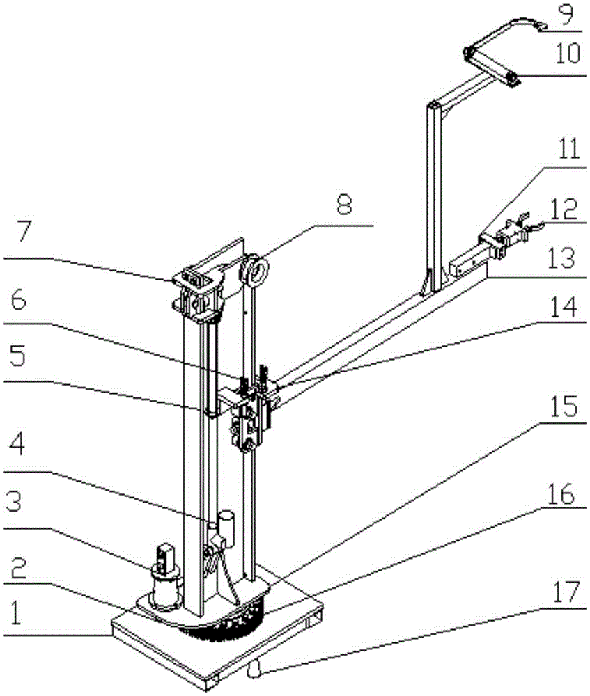
[0008] As shown in the figure, a device for automatically cutting and placing glass tubes is composed of a base 1, a gear 2, a servo motor and a reducer 3, a first cylinder 4, a slide riser 5, a chain 6, and a first sliding device 7 , chain roller 8, cutter 9, second cylinder 10, swing cylinder 11, air claw 12, rectangular steel 13, second sliding device 14, transition plate 15, slewing support 16, adjustment leg 17, slewing support 16 is installed above the base 1, the servo motor and reducer 3 and the slideway vertical plate 5 are installed on the rotary support 16 through the transition plate 15, the first cylinder 4 is installed on the slideway vertical plate 5, and the first sliding device 7 is installed On the left side of the slideway vertical plate 5, and hinged together with the first cylinder 4, the chain roller 8 is installed on the first sliding device 7, the second sliding device 14 is installed on the right side of the slideway vertical plate 5, and the chain 6 is...


PUM


Abstract

The invention provides a device capable of automatically cutting and placing glass tubes, and belongs to the field of electromechanical equipment. The device comprises a base, a gear wheel, a servomotor reductor, a first cylinder, a slideway standing plate, a chain, a first sliding device, a chain roller, a cutter, a second cylinder, an extending and swinging cylinder, an air claw, a rectangular steel strip, a second sliding device, a transitional plate, a reverse support and adjusting supporting legs; the reverse support is arranged above the base; the servomotor reductor and the slideway standing plate are mounted on the reverse support through the transitional plate; the first cylinder is mounted on the slideway standing plate; the first sliding device is mounted on the left side of the slideway standing plate; the chain roller is mounted on the first sliding device; the second sliding device is mounted on the right side of the slideway standing plate; the chain is mounted on the second sliding device; the extending and swinging cylinder, the second cylinder, the air claw and the cutter are mounted on the second sliding device through the rectangular steel. The device has the benefits that the device can automatically cut the glass tubes, and place the glass tubes to assigned positions.

Description

technical field [0001] The invention relates to a device for automatically cutting and placing glass tubes, specifically a device for automatically cutting and placing glass tubes composed of a servo motor, three cylinders, gears and sprocket drives, and belongs to the field of electromechanical equipment. Background technique [0002] Glass tubes are more and more widely used in modern life and engineering, and their weight is generally within 30kg, depending on the type of glass tube. In the production of glass tubes, a very long glass tube needs to be cut off and placed in a designated position. Because there is no automatic cutting and placing device at present, a large number of workers are required to complete it. Modern factory automation processing requires that the cutting and placement of glass tubes should be convenient and flexible, and an automatic device is urgently needed, but there is no such device on the market at present. Contents of the invention [00...

Claims


Application Information

Patent Timeline
Patent Type & Authority Patents(China)
IPC IPC(8): C03B33/06
Inventor 国海芝王玉玲国红云牛春晓唐勇丽宋倩倩王超许红梅杨雯清徐明月李娜孙春燕
Owner 山东广迪教育装备有限公司
Learn More