Fully-automatic cutting device for piston ring

A cutting device and piston ring technology, applied in the direction of piston rings, automatic in/out workpieces, engine components, etc., can solve the problems of low cutting efficiency and high artificial fatigue strength, and achieve high cutting efficiency, good size consistency, and saving The effect of labor costs

Active Publication Date: 2016-03-23
上海谊奥汽配有限公司
View PDF12 Cites 10 Cited by
  • Summary
  • Abstract
  • Description
  • Claims
  • Application Information

AI Technical Summary

Problems solved by technology

[0004] In order to overcome the shortcomings of low cutting efficiency and high artificial fatigue strength of the piston ring cutting equipment in the prior art,

Method used


Image

  • Fully-automatic cutting device for piston ring
  • Fully-automatic cutting device for piston ring
  • Fully-automatic cutting device for piston ring

Examples


Embodiment Construction

[0031] The present invention will be further described below in conjunction with accompanying drawing and specific embodiment:

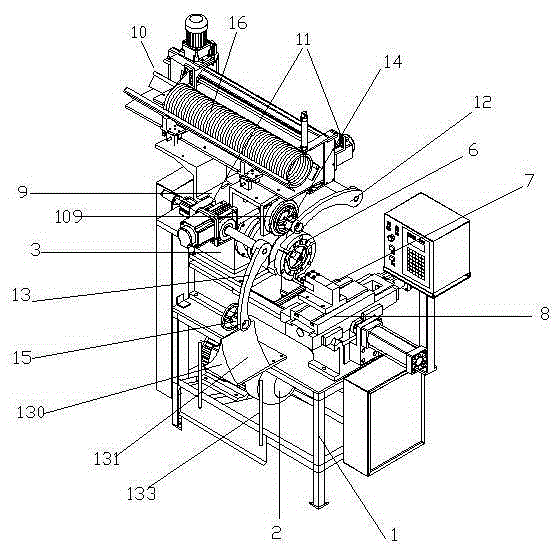
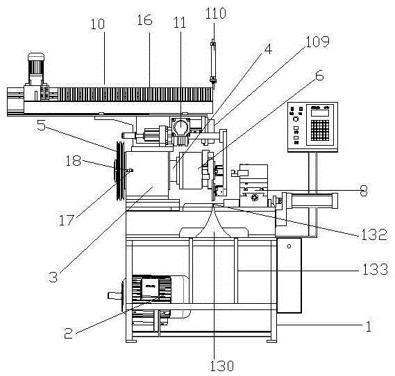
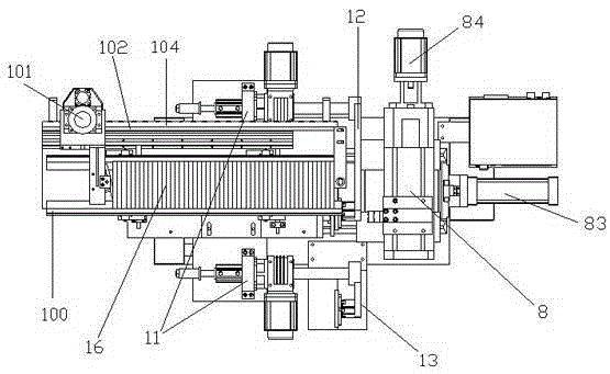
[0032] Such as figure 1 , figure 2 , image 3 with Figure 4 A piston ring full-automatic cutting device shown includes a frame 1, a main motor 2 arranged at the bottom of the frame, a head box 3 is arranged at the left end of the top of the frame, a main shaft 4 is arranged inside the head box 3, and the left end of the main shaft A belt pulley 5 driven by the main motor is provided, a piston ring positioning chuck 6 is provided at the right end of the main shaft, a knife rest 7 is provided at the top right end of the frame, and an automatic knife feed mechanism 8 connected with the frame is provided at the bottom of the knife rest 7. The upper side of headstock box 3 is provided with connecting seat 9, is provided with feeding mechanism 10 on connecting seat 9, is respectively provided with a rotating arm driving assembly 11 on the two sides th...


PUM


Abstract

The invention relates to the technical field of piston ring cutting and discloses a fully-automatic cutting device for a piston ring. The fully-automatic cutting device comprises a frame, a main motor ad a lathe head box, wherein a spindle is arranged in the lathe head box; a belt pulley is arranged at one end of the spindle, and a piston ring positioning chuck is arranged at the other end of the spindle; a knife rest is arranged at the other end of the top of the frame; a connecting base is arranged at the upper side of the lathe head box; a feeding mechanism is arranged on the connecting base; a discharging end of the feeding mechanism is provided with a stopping cylinder; a positioning sleeve is arranged on the side surface of the connecting base; a rotating arm driving assembly is arranged on the connecting base and positioned on each of two sides of the feeding mechanism, wherein a feeding arm is connected to one rotating arm driving assembly, and a discharging arm is connected to the other rotating arm driving assembly; a feeding chunk is arranged at the outer end of the feeding arm; a discharging chuck is arranged at the outer end of the discharging arm; an automatic knife advance mechanism is arranged on the bottom of the knife rest; a distribution frame is arranged at a position, right below the discharging chuck, of the frame. The fully-automatic cutting device is high in cutting efficiency and high in cutting precision while used for cutting the piston ring.

Description

technical field [0001] The invention relates to the technical field of piston ring cutting, in particular to a fully automatic cutting device for piston rings. Background technique [0002] There is a wear-resistant ring in the piston ring. The wear-resistant ring is made by casting and needs to be cut into two pieces after being made. The traditional processing method is through lathe processing. After the piston ring is clamped by the chuck of the lathe, the knife is set, cut, and then the two cut rings are removed, and then the piston ring is installed, so the cycle works. Obviously, this kind of operation method has high artificial fatigue intensity, and the cutting efficiency of piston rings is low. It is necessary to set the knife and cut each time. After cutting the same batch of piston rings, there are differences in thickness, and the product consistency is poor. [0003] Chinese patent application number: CN201010536927.9, application date November 2, 2010, disclo...

Claims


Application Information

Patent Timeline
IPC IPC(8): B23B5/00B23B15/00B23B31/103
CPCB23B5/00B23B31/103B23B2215/247B23Q7/00B23Q2707/003
Inventor 江树强
Owner 上海谊奥汽配有限公司
Why Eureka
Try Eureka