Fixed-length water jet cutting machine for metal pipe

A technology for metal pipes and cutting machines, applied in metal processing equipment, pipe shearing devices, shearing devices, etc., which can solve problems such as prone to errors, lack of transmission devices, time-consuming and labor-intensive problems

Inactive Publication Date: 2016-03-16
TIANJIN XINDAYUAN METAL PROD
View PDF0 Cites 10 Cited by
  • Summary
  • Abstract
  • Description
  • Claims
  • Application Information

AI Technical Summary

Problems solved by technology

[0002] At present, with the development of the modern mechanical processing industry, the requirements for cutting quality and precision are continuously improved, and the requirements for improving cutting efficiency and reducing cutting time are also increasing. In the process of metal pipe processing, most factories use waterjet cutting. However, the function of the traditional water jet cutting machine is very single, and the cutting length needs to be manually measured and controlled, which is very time-consuming and laborious, resulting in low cutting efficiency; and the traditional water jet

Method used


Image

  • Fixed-length water jet cutting machine for metal pipe
  • Fixed-length water jet cutting machine for metal pipe

Examples


Embodiment 1

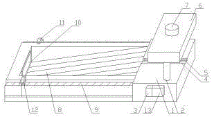
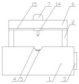
[0011] A metal pipe fixed-length waterjet cutting machine, comprising: cutting table 1, support column 2, controller 3, storage tank 4, steel conveyor belt 5, water knife holder 6, high-pressure pump 7, blanking bin 8, card slot 9. Dryer 10, infrared transmitter 11, infrared receiver 12, counter 13, water knife head 14, slide rail 15, support column 2 is installed above the cutting table 1, water knife holder 6 is installed above the support column 2, water knife A high-pressure pump 7 is installed above the frame 6, a slide rail 15 is installed under the water jet frame 6, a water jet head 14 is installed on the slide rail 15, a storage tank 4 is opened above the cutting table 1, a steel conveyor belt 5 is installed at the bottom of the storage tank 4, and a cutting table 1 Controller 3 is installed on one side, counter 13 is installed on one side of controller 3, blanking bin 8 is installed on one side of cutting table 1, dryer 10 is installed on one side of blanking bin 8, c...

Embodiment 2

[0013] Place the metal pipe with cutting on the storage slot 4, adjust the position of the infrared transmitter 11 and the infrared receiver 12 on the slot so that the distance from the cutting table 1 is equal to the length of the cutting metal pipe, and turn on the power to make the device run. The quality conveyor belt 5 moves the metal tube to the direction of the blanking bin 8. When the metal tube reaches the cutting length, it blocks the infrared transmitter 11, so that the infrared receiver 12 cannot receive the infrared signal, and triggers the controller 3 and the counter 13. Counting once, at the same time the controller 3 stops the steel conveyor belt 5 from moving, the high-pressure pump 7 runs, the water jet head 14 moves laterally on the slide rail 15, and cuts the metal pipe. After cutting, the front section of the metal pipe falls into the blanking bin 8 Inside, the dryer 10 dries the metal tube in the blanking bin 8, the infrared emitter 11 loses its shield, a...


PUM


Abstract

A fixed-length water jet cutting machine for a metal pipe comprises a cutting table, a water jet cutter rack and the like. The fixed-length water jet cutting machine is characterized by further comprising supporting columns, a controller, a storage groove, a steel conveying belt, a blanking bin, clamping grooves, a drier, an infrared emitter, an infrared receiver, a counter and a sliding rail. The supporting columns are installed on the cutting table. The water jet cutter rack is installed on the supporting columns. The storage groove can fix the metal pipe to be cut, so that the position of the metal pipe is prevented from changing in the moving process. The metal pipe to be cut can be moved to a cutting position through the steel conveying belt, and a lot of time and labor are saved. The residual moisture content can be dried through the drier, and the metal pipe is prevented from being corroded by the residual moisture content on the surface of the metal pipe. When the infrared emitter and the infrared receiver are blocked by the metal pipe, a controller is triggered, the metal pipe is cut through the water jet cutter, automatic counting is achieved by the counter at the same time, and automatic cutting is achieved; in addition, the adjustable infrared emitter and the infrared receiver are located in the clamping grooves, and automatic fixed-length cutting is achieved.

Description

technical field [0001] The invention relates to the field of metal pipe processing, in particular to a fixed-length water jet cutting machine for metal pipes. Background technique [0002] At present, with the development of the modern mechanical processing industry, the requirements for cutting quality and precision are continuously improved, and the requirements for improving cutting efficiency and reducing cutting time are also increasing. In the process of metal pipe processing, most factories use waterjet cutting. However, the function of the traditional water jet cutting machine is very single, and the cutting length needs to be manually measured and controlled, which is very time-consuming and laborious, resulting in low cutting efficiency; and the traditional water jet cutting machine does not have any counting settings, and the staff need to count them manually during the cutting process, which is very difficult Errors are prone to occur; there is no transmission de...

Claims


Application Information

Patent Timeline
IPC IPC(8): B23D21/00B23D79/00B23D33/02B23D33/12
CPCB23D21/00B23D33/02B23D33/12B23D79/00
Inventor 李悦勇
Owner TIANJIN XINDAYUAN METAL PROD
Why Eureka
Try Eureka