Step-type self-sealing waste heat recovery system

A waste heat recovery system and self-sealing technology, applied in the field of waste heat recovery of flue gas, can solve the problems of reducing the taste of waste heat flue gas, excessive length-width ratio of hot air hood, affecting the performance of waste heat power station, etc. The effect of cooling air and improving the recovery rate of waste heat

Active Publication Date: 2014-10-15
广州市瑞溥能源环保科技有限公司
View PDF4 Cites 1 Cited by
  • Summary
  • Abstract
  • Description
  • Claims
  • Application Information

AI Technical Summary

Problems solved by technology

Based on the characteristics of the hot air hood of the cooling machine and the trolley moving and resting, there is a gap of 5cm to 10cm between the hood and the trolley. After the boiler induced draft fan of the waste heat power plant is turned on, a slight negative pressure is formed inside the hot air hood, which leads to A large amount of cold air outside the hot air hood is sucked into the hot air hood through this gap, which greatly reduces the taste of the waste heat flue gas and seriously affects the efficiency of the waste heat power station
At the same time, because the cooling machine can use the waste heat to gradually drop the temperature of each section from 500°C to about 200°C, the length-to-width ratio of the hot air hood in this section is too large, so that under the suction of the waste heat boiler induced fan, the flue gas in the entire hot air hood The flow field is in a state of turbulent flow and vortices are generated locally, and a large amount of high-temperature flue gas cannot enter the waste heat boiler through the hot air outlet and be recycled.

Method used


Image

  • Step-type self-sealing waste heat recovery system
  • Step-type self-sealing waste heat recovery system
  • Step-type self-sealing waste heat recovery system

Examples


Embodiment 1

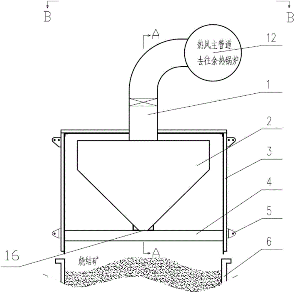
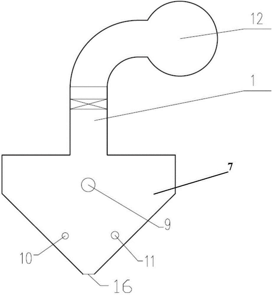
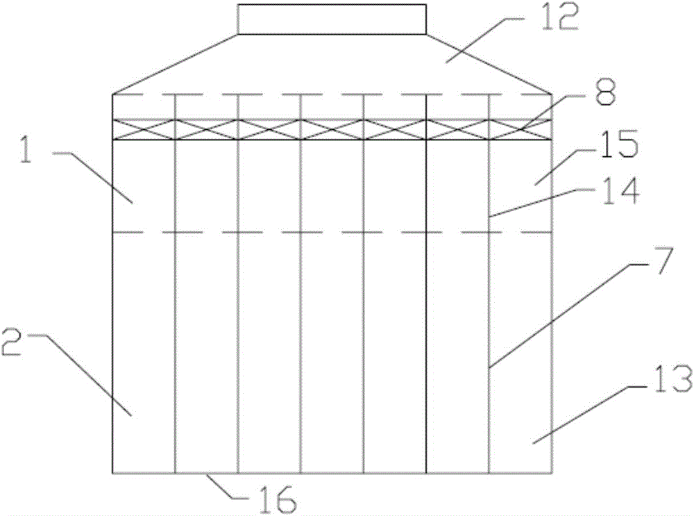
[0016] like figure 1 , figure 2 and image 3 As shown, the stepped self-sealing waste heat recovery system of this embodiment includes a hot blast cover 3 and a hot blast piping system 12. The hot blast piping system can be connected to the waste heat boiler, and the hot blast cover can cover the sintered ore of the sintering cooling trolley 6. There is also a built-in flue 2 inside the hot air hood, and a flue gas outlet 1 is arranged on the hot air hood. The built-in flue 2, the flue gas outlet 1 and the hot air piping system 12 are sequentially connected. For the long and narrow suction port 16 for extracting hot air, the built-in flue 2 is divided into several sub-built-in flues 13 by several flue partitions 7 along the length direction of the suction port, and the flue partition 7 is perpendicular to the length direction of the suction port 16 , the suction port is also divided into several sub-suction ports by the flue partition, and each sub-built-in flue has an inde...


PUM


Abstract

The invention discloses a step-type self-sealing waste heat recovery system which comprises a hot air hood and a hot air pipeline system, wherein the hot air hood is internally provided with a built-in flue; the hot air hood is provided with a fume sucking port; the built-in flue, the fume sucking port and the hot air pipeline system are sequentially connected; the lower part of the built-in flue is provided with a strip-shaped air sucking port for sucking hot air; the built-in flue is divided into a plurality of built-in sub-flues by a plurality of flue partitions along the length direction of the air sucking port; each built-in sub-flue is provided with an independent air sucking sub-port; the fume sucking port is internally divided into fume sucking sub-ports corresponding to the built-in sub-flues by a plurality of fume sucking port partitions; the built-in sub-flues are communicated with the corresponding fume sucking sub-ports. The step-type self-sealing waste heat recovery system is capable of effectively preventing external environments from influencing the waste heat recovery system, preventing external cold air from being sucked, eliminating a fume turbulent condition in the hot air hood, greatly improving the fume waste heat recovery rate of a sintering cooling machine and achieving the purpose of fully utilizing waste heat resources.

Description

Technical field: [0001] The invention belongs to the field of flue gas waste heat recovery, and in particular relates to a stepped self-sealing waste heat recovery system which can improve the waste heat recovery efficiency of a sintering cooler. Background technique: [0002] Since my country introduced sinter cooler waste heat power generation technology from abroad in the late 1990s, after more than 10 years of development, many sinter cooler waste heat power stations have been built in China. But so far, most power plants have fallen far short of expected performance indicators. The root cause is that the biggest technical difficulty lies in the air leakage treatment between the hot air hood of the sintering cooler and the trolley and the flow field control of the high-temperature flue gas in the hot air hood. Based on the characteristics of the hot air hood of the cooling machine and the trolley moving and resting, there is a gap of 5cm to 10cm between the hood and the...

Claims


Application Information

Patent Timeline
Patent Type & Authority Applications(China)
IPC IPC(8): F27D17/00
Inventor 郑泽群
Owner 广州市瑞溥能源环保科技有限公司
Why Eureka
Try Eureka