An Optimal Design Method for Single Aperture Multi-beam Antenna

A multi-beam antenna and optimized design technology, applied to antennas, electrical components, etc., can solve problems such as high side lobes, low beam overlap gain, and low beam C/I, achieving low technical difficulty and facilitating engineering implementation. good performance effect

Active Publication Date: 2016-07-06
XIAN INSTITUE OF SPACE RADIO TECH
View PDF4 Cites 6 Cited by
  • Summary
  • Abstract
  • Description
  • Claims
  • Application Information

AI Technical Summary

Problems solved by technology

[0008] The technical problem to be solved by the present invention is: to overcome many problems existing in the existing single-aperture multi-beam antenna, such as high side lobe, low beam overlap gain, scanning beam deformation, and low beam C / I, and propose a single-aperture multi-beam antenna The optimal design method of this method can realize high-gain, low-sidelobe transmit-receive shared multi-beam with relatively low technical difficulty

Method used


Image

  • An Optimal Design Method for Single Aperture Multi-beam Antenna
  • An Optimal Design Method for Single Aperture Multi-beam Antenna
  • An Optimal Design Method for Single Aperture Multi-beam Antenna

Examples


Embodiment Construction

[0046] The optimization design method of the single-aperture multi-beam antenna according to the present invention will be further described in detail in conjunction with the accompanying drawings and specific embodiments.

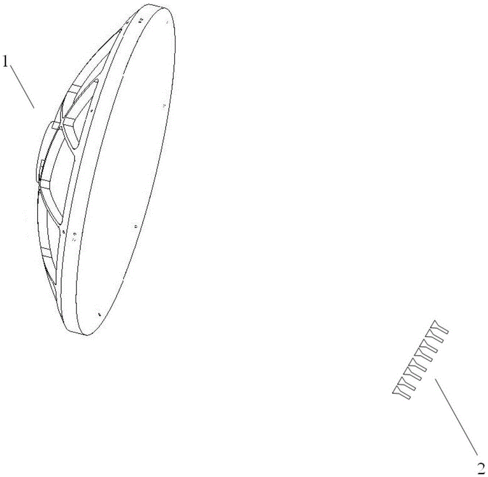
[0047] Such as figure 2 As shown, the single-aperture multi-beam antenna according to the present invention includes a reflector 1 and a feed source array 2 . Wherein, the feed source array 2 includes a plurality of light wall-shaped horns with identical structures and dimensions, and the feed source array 2 is located in front and below the reflector 1 .

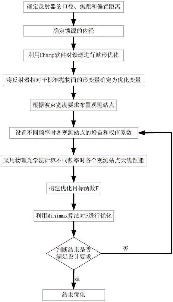
[0048] refer to figure 1 and figure 2 , the method according to the present invention comprises the following steps:

[0049] (S1) Determine the aperture D, focal length F, and offset distance H of the reflector according to the requirements of the design index.

[0050] The size of the aperture D of the reflector depends on the designed beam width θ 3dB , the design requirements of the working w...


PUM


Abstract

The invention relates to an optimal design method of a single-aperture multi-beam antenna. The antenna includes a reflector and a feed source array. The method optimizes the shape of the reflection surface, widens the antenna beam under the premise that the side lobe rises small, and improves the performance of the antenna. The overlapping gain of the beam is improved, and the contradiction between the overlapping gain and the side lobe level of the traditional single-aperture single-feed multi-beam antenna is solved, and the index requirements of the receiving and transmitting beams are taken into account during the optimization process, and the single-aperture single-source The feed sub-beam forming method realizes a high-gain, low-sidelobe common beam for transmitting and receiving.

Description

technical field [0001] The invention belongs to the technical field of space-borne antennas, and in particular relates to an optimal design method of a single-aperture multi-beam antenna. Background technique [0002] With the rapid growth of demand for satellite broadband multimedia services, the relatively idle Ka frequency band has become the preferred frequency band for high-definition TV and broadband multimedia two-way services around the world instead of C and Ku frequency bands. In order to make full use of limited spectrum and power resources, Ka broadband communication satellites mainly adopt the form of multi-beam antennas. [0003] Spaceborne multi-beam antennas mainly include direct phased array antennas and reflector + feed array antennas. The beam forming network of the direct phased array antenna is complicated. When multiple beams are formed, the channel components are multiplied, which eventually leads to the weight, power consumption and heat consumption ...

Claims


Application Information

Patent Timeline
Patent Type & Authority Patents(China)
IPC IPC(8): H01Q19/12
Inventor 张新刚丁伟万继响王旭东陶啸安啸
Owner XIAN INSTITUE OF SPACE RADIO TECH
Why Eureka
Try Eureka