Low maintenance nozzle mixer unit for roll nip lubrication

一种轧辊间隙、混合器的技术,应用在轧辊的装置领域,能够解决损坏轧制带材表面品质、润滑失效等问题

Active Publication Date: 2014-10-15
PRIMETALS TECH AUSTRIA GMBH
View PDF7 Cites 3 Cited by
  • Summary
  • Abstract
  • Description
  • Claims
  • Application Information

AI Technical Summary

Problems solved by technology

In this way, the roll gap lubrication in the nozzle segments is completely ineffective, which can significantly impair the surface quality of the rolled strip

Method used


Image

  • Low maintenance nozzle mixer unit for roll nip lubrication
  • Low maintenance nozzle mixer unit for roll nip lubrication
  • Low maintenance nozzle mixer unit for roll nip lubrication

Examples


Embodiment Construction

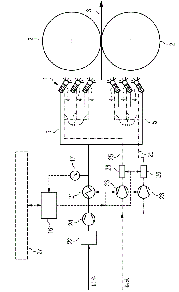
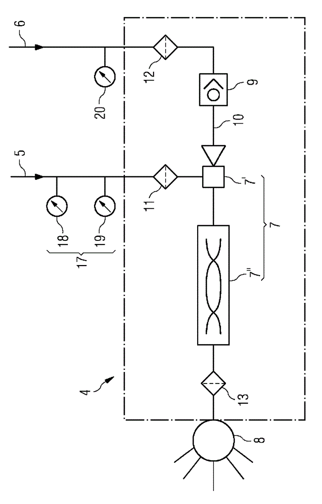
[0022] figure 1 A block diagram of roll gap lubrication according to the invention is shown. Reference numeral 1 designates a mixing and spraying device, which is formed from a plurality of nozzle mixer units 4 . An emulsion of water and oil is introduced into the roll gap by means of the nozzle mixer unit 4 . This is done by means of the nozzles 8 of the nozzle mixer unit 4 (see figure 2 ) spray the emulsion onto the work roll 2 and / or onto the surface of the rolled strip 3 .

[0023] Each nozzle mixer unit 4 is supplied with water via a first supply line 5 and with oil via a second supply line 6 . Nozzle and mixer form a structural unit.

[0024] The oil supply lines to the mixing and injection device (1) lead in a line bundle (25). The oil lines are supplied by individual pump elements and / or via oil valves, which operate on and off or continuously. In this way, a uniform or individual oil flow loading can be used for each nozzle mixer unit, eg also 0% loading.

[0...


PUM


Abstract

The invention relates to a device for lubricating the cylinders of a roll stand, in particular for roll nip lubrication in a roll stand for strip-shaped rolling stock. A mixture made out of water and oil is produced by means of a mixing and spraying device (1). Said mixture is sprayed onto at least one of the cylinders (2) of the roll stand and / or to the surface of the rolling stock (3). The mixer and the spraying device (1) consists of an arrangement consisting of several nozzle mixer units (4), water being guided thereto by means of a first supply line (5) and oil being guided thereto by means of a second supply line (6).

Description

technical field [0001] The invention relates to a device for lubricating the rolls of a rolling stand, in particular for roll gap lubrication in a rolling stand for strip-shaped rolled material, wherein the A mixture of water and oil is sprayed onto at least one of the rolls of the rolling mill stand and / or onto the surface of the rolled material. Background technique [0002] It is known that in the manufacture of metal strip the surface quality of the metal strip can be improved when the coefficient of friction between the work rolls and the rolled material is reduced. The introduction of a lubricant, for example, during the production of the metal strip not only requires less energy for the rolling process, but also increases the service life of the work rolls of the rolling stand. [0003] Usually an emulsion of oil and water is used for roll gap lubrication. The emulsion is created in a mixing device. To this end, the mixing device is supplied with oil and water via ...

Claims


Application Information

Patent Timeline
Patent Type & Authority Applications(China)
IPC IPC(8): B21B27/10
CPCB21B45/0251B01D35/02B21B45/0248B21B45/0242B21B27/10
Inventor T.布赖特R.卡尔
Owner PRIMETALS TECH AUSTRIA GMBH
Why Eureka
Try Eureka