Thrust reverser with pivoting grilles

A technology of thrust reverser and pivoting, which is applied in the direction of jet propulsion device, machine/engine, high-efficiency propulsion technology, etc., to achieve the effect of reducing radial load

Inactive Publication Date: 2014-10-22
AIRCELLE
View PDF6 Cites 12 Cited by
  • Summary
  • Abstract
  • Description
  • Claims
  • Application Information

AI Technical Summary

Problems solved by technology

[0014] - Additional complexity and weight created by the need to provide drive cylinders for each radially inner cascade

Method used


Image

  • Thrust reverser with pivoting grilles
  • Thrust reverser with pivoting grilles
  • Thrust reverser with pivoting grilles

Examples


Embodiment Construction

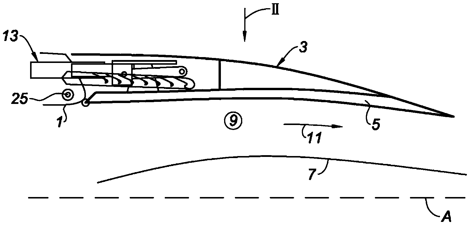
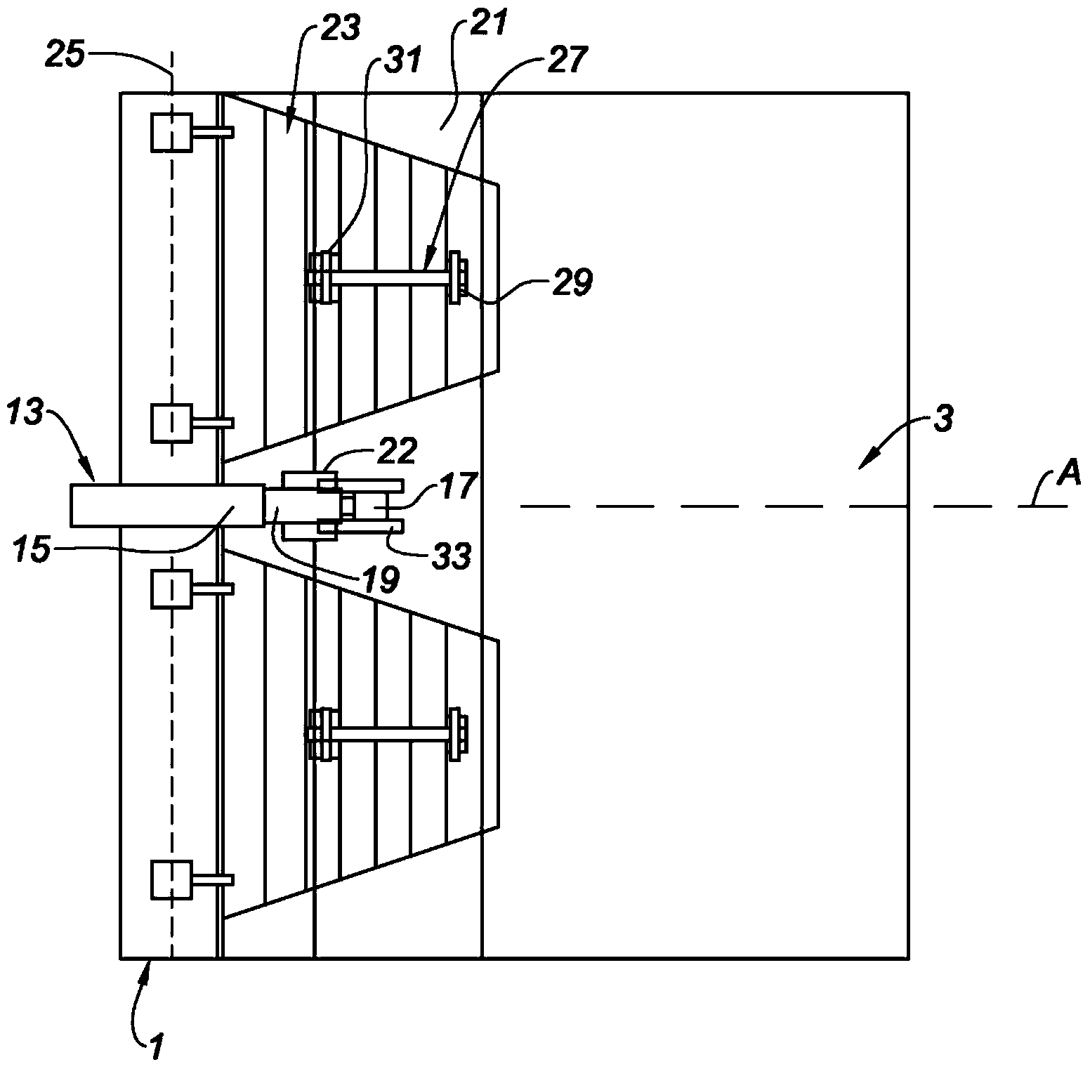
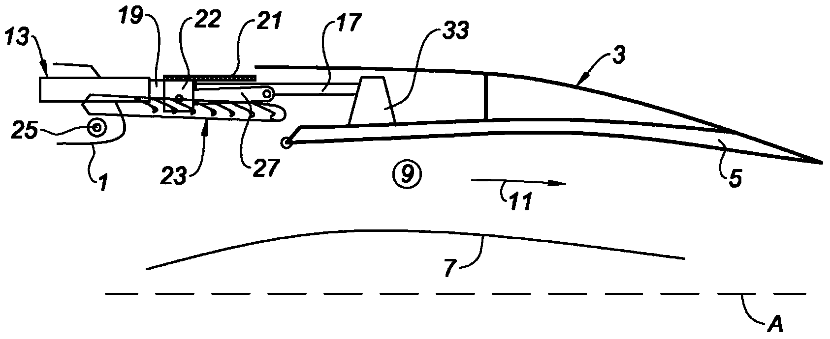
[0037] now refer to figure 1 and 2 , where it can be seen that the thrust reverser according to the invention comprises a fixed front frame 1 integrated into the fixed structure of the nacelle or the casing of the engine fan, and a fairing 3 slidably mounted relative to said fixed structure, e.g. , mounted to rails located on the upper beam (often referred to as "6 o'clock") and lower beam (often referred to as "12 o'clock") of the nacelle.

[0038] On its inner surface, the sliding fairing 3 comprises a coating 5 with sound-absorbing properties, which can in particular be formed in a honeycomb structure covered with a perforated skin.

[0039] The sliding cowl 3 and the cowling 7 surrounding the turbojet engine (not shown) define a cold air flow path 9, which is directed in the direction of the arrow 11 and ensures most of the thrust of the propulsion assembly formed by the nacelle and its turbojet engine .

[0040] sliding cover 3 in as figure 1 and 2 The location shown...


PUM


Abstract

This grid thrust reverser (23) for an aircraft turbojet engine comprises a front frame (1), a sliding cover (3) which slides between a direct jet position and a reverse jet position, a plurality of actuating cylinders (13) interposed between said front frame (1) and said sliding cover (3), and a plurality of grilles (23) mounted pivotably on the front frame (1) between a direct jet position, wherein said grilles (23) are substantially parallel to the axis (A) of the thrust reverser, and a reverse jet position, wherein said grilles are inclined relative to the axis (A) of the thrust reverser, characterised in that it comprises a single radial layer of grilles (23).

Description

technical field [0001] The invention relates to a thrust reverser of the cascade type for an aircraft turbojet engine, and to a nacelle of an aircraft turbojet engine equipped with such a thrust reverser. Background technique [0002] It is known that a nacelle for an aircraft turbojet engine constitutes the aerodynamic fairing of said turbojet engine and can further fulfill many functions, wherein the thrust reversal function can be realized when said nacelle is equipped with a thrust reverser . [0003] This thrust reverser allows, when the aircraft is on the ground, to deflect at least part of the air flow upstream of the nacelle produced by the turbojet engine (a configuration known as "reverse injection"), and thus contributes greatly to the control of the aircraft. This reduces the distance required for the aircraft to come to a complete stop. [0004] In the prior art, there are two main classes of thrust reversers: portal thrust reversers, and cascade thrust revers...

Claims


Application Information

Patent Timeline
Patent Type & Authority Applications(China)
IPC IPC(8): F02K1/72
CPCF02K1/72Y02T50/671Y02T50/60
Inventor 帕特里克·哥诺迪克劳伦特·艾伯特·布兰奥利维尔·凯尔布莱尓
Owner AIRCELLE
Why Eureka
Try Eureka