Supercharge Your Innovation With Domain-Expert AI Agents!

Determination of Impairment Compensation Matrix of Antenna Array

A technology of impairment compensation matrix and antenna array, applied in antennas, electrical components, transmitter monitoring, etc., to simplify and reduce design time, optimize properties, and improve system throughput

Inactive Publication Date: 2016-08-17
OPTIS CELLULAR TECH LLC
View PDF3 Cites 0 Cited by
  • Summary
  • Abstract
  • Description
  • Claims
  • Application Information

AI Technical Summary

Problems solved by technology

Alternatively, the effect of mutual coupling can simply be ignored, which results in a non-ideal radiation pattern

Method used


Image

  • Determination of Impairment Compensation Matrix of Antenna Array
  • Determination of Impairment Compensation Matrix of Antenna Array
  • Determination of Impairment Compensation Matrix of Antenna Array

Examples


Embodiment Construction

[0034] The embodiments set forth below represent the necessary information to enable one skilled in the art to practice the embodiments and set forth the best modes for practicing the embodiments. After reading the following description in light of the accompanying drawing figures, those skilled in the art will understand the concepts of the disclosure and will recognize applications of these concepts not particularly addressed herein. It should be understood that these concepts and applications fall within the scope of this disclosure and the appended claims.

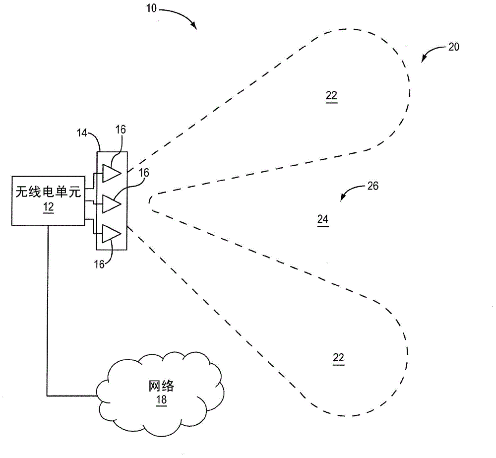
[0035] Before delving into the details of the embodiments, a context of the environment in which the embodiments may be implemented will be provided. figure 1is a block diagram of a system 10 in which embodiments may be implemented. System 10 includes radio unit 12 coupled to antenna array 14 . Radio unit 12 may include any processing or computing device capable of generating and providing signals to antenna array 14...


PUM


Abstract

Determination of an impairment compensation matrix for compensating for impairments in an antenna array is disclosed. A plurality of different combinations of multiple signal transmissions forming at least one null at respective ones of the plurality of locations are determined. Each combination includes: a multiple signal transmission comprising at least two simultaneous signal transmissions from at least two of the N antenna subarrays; and said corresponding location. An impairment matrix identifying effects of impairments across the N antenna subarrays is determined based on signal characteristics associated with the plurality of different combinations of multi-signal transmissions and expected signal reception at the plurality of locations. The impairment compensation matrix is ​​determined based on the impairment matrix.

Description

[0001] related application [0002] This application claims priority to Provisional Patent Application Serial No. 61 / 597,903, filed February 13, 2012, the disclosure of which is hereby incorporated by reference in its entirety. technical field [0003] Embodiments relate generally to wireless communications and, in particular, to the determination of an impairment compensation matrix that compensates for antenna impairments, such as mutual coupling between antenna sub-arrays of an antenna array. Background technique [0004] Advanced wireless communication systems, such as multiple-input multiple-output (MIMO) communication systems, increasingly rely on simultaneous signal transmission from multiple antenna sub-arrays of an antenna array to form a desired radiation pattern. An antenna subarray may consist of one or more antenna elements. In theory, by changing the signal characteristics of the simultaneously transmitted signals, eg by changing the phase or amplitude of the ...

Claims


Application Information

Patent Timeline
Patent Type & Authority Patents(China)
IPC IPC(8): H04B17/12
CPCH04B17/12H01Q3/40
Inventor 尼尔·麦高恩马蒂尼斯·W·达西尔维拉波·葛兰松皮特·迪恩
Owner OPTIS CELLULAR TECH LLC
Features
  • R&D
  • Intellectual Property
  • Life Sciences
  • Materials
  • Tech Scout
  • Unparalleled Data Quality
  • Higher Quality Content
  • 60% Fewer Hallucinations
Learn More