Corneal curvature measuring device based on telecentric light path system

A telecentric optical path and curvature measurement technology, used in eye testing equipment, medical science, diagnosis, etc., can solve the problems of inaccurate corneal curvature value and difficulty in focusing on the z-axis, and achieve precise focusing and improve measurement accuracy. , the effect of improving the focusing speed

Active Publication Date: 2014-10-29
TAIYUAN XINYUAN HIGH-TECH CENT NORTH UNIV OF CHINA
View PDF7 Cites 7 Cited by
  • Summary
  • Abstract
  • Description
  • Claims
  • Application Information

AI Technical Summary

Problems solved by technology

[0003] The present invention is aimed at the problem that the obtained corneal curvature value is not accurate enough because it is difficult to achieve high-precision

Method used


Image

  • Corneal curvature measuring device based on telecentric light path system
  • Corneal curvature measuring device based on telecentric light path system
  • Corneal curvature measuring device based on telecentric light path system

Examples


Embodiment 1

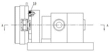
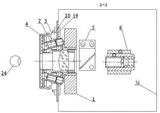
[0025] A corneal curvature measurement device based on a telecentric optical path system, such as figure 2 , it consists of objective lens device 1, light spot collimation device 2, ring lighting device 3, ring device 4, monitoring spectroscopic mirror device 5, monitoring system device 6 and base plate 36. The exit pupil of the autorefractor is located in front of the central hole of the bull ring device 4, wherein, such as Figure 4 , the objective lens device 1 comprises an objective lens holder 7, an objective lens barrel 8 and an objective lens 9, the objective lens 9 holder 7 is fixed on the base plate 36, the objective lens barrel 8 is fixed on the objective lens holder 7 by a screw 10, and the objective lens 9 is fixed by a pressure cylinder In the objective lens barrel 8; as Figure 5 There are two light spot collimation devices 2 arranged symmetrically about the center of the objective lens barrel 8, and the light spot collimation device 2 is inclined at 10 degrees...

Embodiment 2

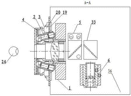
[0027] A corneal curvature measurement device based on a telecentric optical path system, such as image 3 , it is made up of objective lens device 1, spot collimation device 2, ring illumination device 3, ring device 4, monitoring spectroscopic mirror device 5, reflector device 33, monitoring system device 6 and base plate 36, when starting measurement , the human eyeball is located at the exit pupil of the automatic refractor, that is, in front of the central hole of the bull ring device 4, wherein, as Figure 4 , objective lens device 1 comprises objective lens mount 7, objective lens barrel 8 and objective lens 9, objective lens 9 mounts 7 are fixed on the base plate 36, objective lens barrel 8 is fixed on the objective lens mount 7 by screw 10, objective lens 9 is fixed by wire loop In the objective lens barrel 8; as Figure 5 There are two light spot collimation devices 2 arranged symmetrically about the center of the objective lens barrel 8, and the light spot collimat...


PUM


Abstract

The invention relates to a corneal curvature measuring device based on a telecentric light path system. The corneal curvature measuring device is composed of an objective lens device, a light spot collimation device, a target ring illuminating device, a target ring device, a monitoring beam splitter device, a monitoring system device and a base board. The objective lens device comprises an objective lens fixing base, an objective lens cone and an objective lens. The light spot collimation device comprises a light spot collimation lens cone, a light source circuit board, a light emitting diode, a diffuser, a small aperture and a collimation lens. The target ring illuminating device comprises a target ring illuminating circuit board and at least three illuminating light emitting diodes. The target ring device comprises a target ring fixing support, a target ring and a target ring protection piece. The monitoring beam splitter device comprises a monitoring beam splitter base and a monitoring beam splitter. The monitoring system device comprises a monitoring fixing support, a monitoring lens cone, a monitoring lens and an aperture pressing cylinder. According to the corneal curvature measuring device, the measuring accuracy of the corneal curvature and the focusing speed of a full-automatic computer optometry unit are greatly improved.

Description

technical field [0001] The invention belongs to a fully automatic computer refractometer, in particular to a corneal curvature measuring device based on a telecentric optical path system. Background technique [0002] The measurement of corneal curvature requires high precision. The optical lens group usually used in the current corneal curvature measurement device can clearly image the human cornea, and the calculation of the size of the reflection image of the illumination ring and the change of the image gray level through the cornea with different curvatures , it is easy to achieve focusing in the horizontal x direction and vertical y direction, but in the focusing along the optical axis z direction, because the imaging quality and image sharpness near the optical focal plane are similar, it is difficult to achieve higher precision z Axis focusing, resulting in small changes in the size of the corneal ring image, which in turn makes the calculated corneal curvature inacc...

Claims


Application Information

Patent Timeline
IPC IPC(8): A61B3/107
Inventor 陈友华杜晓军阎洁赵俊奇郭智勇
Owner TAIYUAN XINYUAN HIGH-TECH CENT NORTH UNIV OF CHINA
Why Eureka
Try Eureka