
Spiral conveying cleaning process

A spiral conveying and spiral technology, applied in the field of spiral conveying cleaning technology, can solve problems such as affecting the drying effect of the drying section, and achieve the effect of improving the cleaning effect.

Active Publication Date: 2016-12-28
SHENZHEN KAIZHONG PRECISION TECH CO LTD
View PDF8 Cites 0 Cited by
  • Summary
  • Abstract
  • Description
  • Claims
  • Application Information

AI Technical Summary

Problems solved by technology

[0009] For this reason, the technical problem to be solved by the present invention is to overcome the problem that the cleaning liquid in the cleaning part of the prior art spiral conveying cleaning device flows to the drying section, which affects the drying effect of the drying section, and provides a drying section setting Outside the spiral conveying drum, it does not affect the cleaning and cleaning part to transport the material to the drying section for drying, and prevents the cleaning liquid from the cleaning part from entering the drying section.

Method used

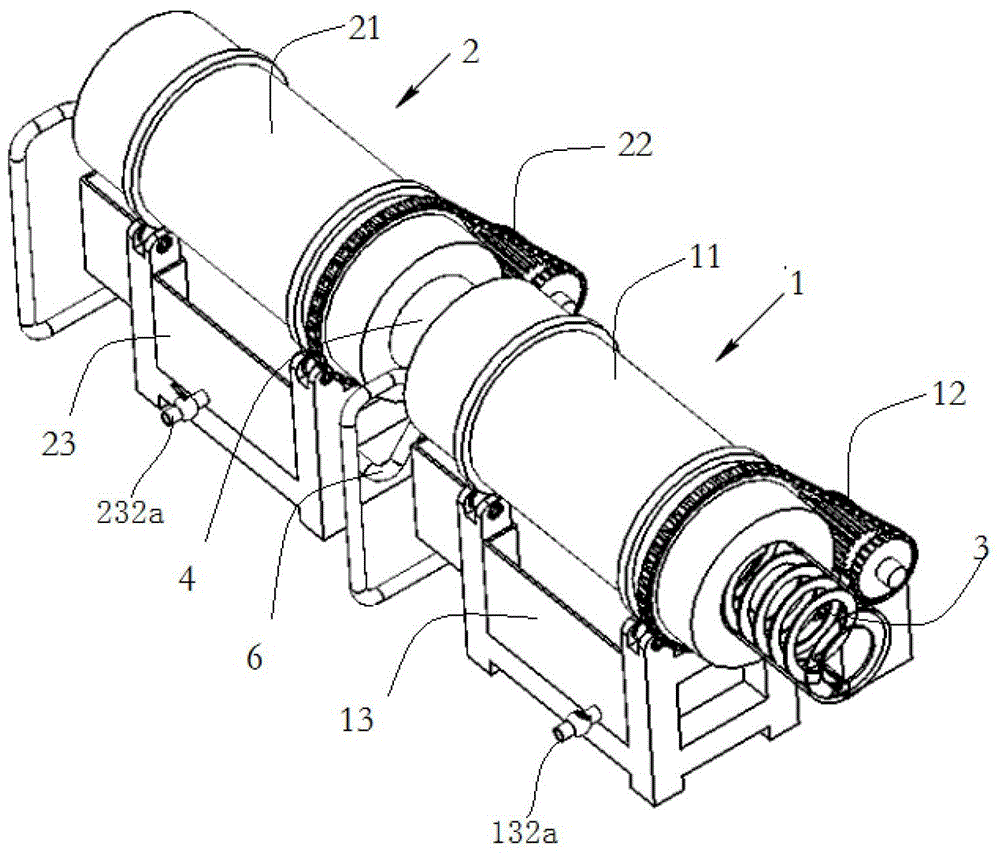

Image

  • Spiral conveying cleaning process
  • Spiral conveying cleaning process
  • Spiral conveying cleaning process

Examples


Embodiment 1

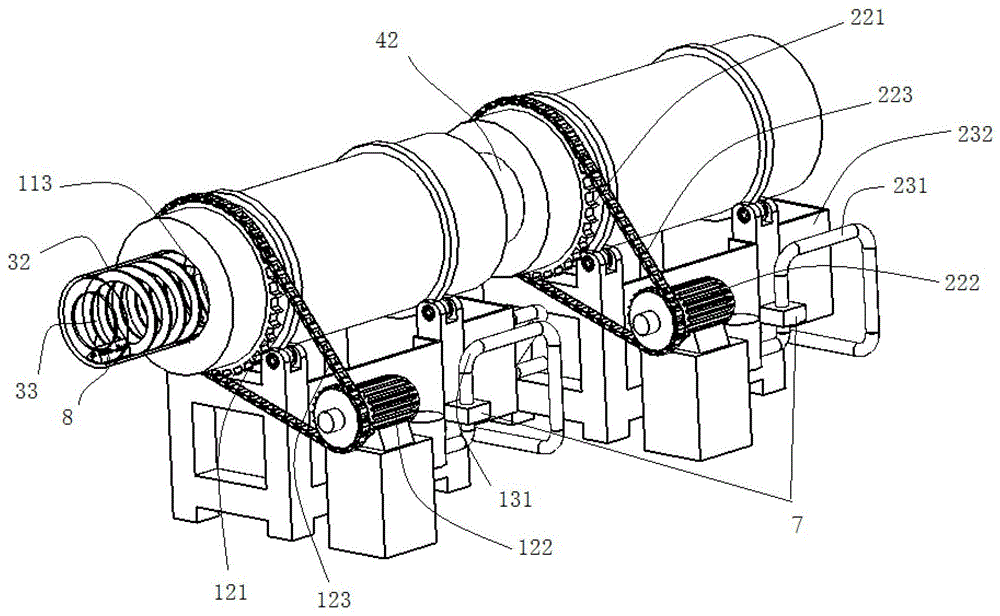
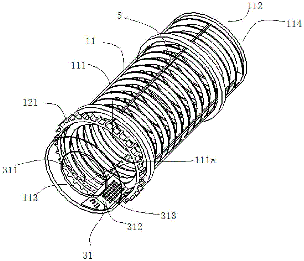
[0047] Such as figure 1 , 2 As shown, this embodiment provides a spiral conveying and cleaning device, including a spiral conveying and cleaning mechanism 2 for receiving and cleaning the materials conveyed by the previous process, and conveying the cleaned materials to the rinsing process; It includes a screw conveying and rinsing mechanism 1, which is arranged at the outlet of the spiral conveying and cleaning mechanism, and is used for receiving and rinsing the materials conveyed by the spiral conveying and cleaning mechanism, and outputting the rinsed materials. The conveying and rinsing mechanism 1 includes a first screw conveying drum 11, the first spiral conveying drum 11 includes a first spiral passage 111 arranged along its inner wall, and the first spiral conveying rollers arranged at both ends of the first spiral passage 111 The first conveying inlet 112 and the first conveying outlet 113 of the rinsing mechanism 2; the first revolving conveying assembly 3 is used ...

Embodiment 2

[0064] This embodiment provides a process for cleaning materials using the screw conveying cleaning device described in Embodiment 1, including the following steps:

[0065] A. The step of cleaning and conveying the material by the screw conveying cleaning mechanism 2: the material of the spiral conveying cleaning mechanism 2 is received by the feeding device (the feeding device described here is the previous process of the screw conveying cleaning mechanism) For the conveyed material, the material receiving port of the screw conveying cleaning mechanism 2 corresponds to the material output port of the feeding device, and the spiral conveying cleaning mechanism 2 conveys the received material to its outlet through the spiral conveying method , and during the transportation process, the material is cleaned to remove the oil or rust on the surface of the material, and the material is output after the oil or rust is removed.

[0066] In the present invention, immediately after st...


PUM


Abstract

The invention discloses a screw conveying and cleaning process. In the screw conveying and cleaning process, a screw conveying and cleaning mechanism (2) and a screw conveying and rinsing mechanism (1) are jointly adopted, wherein the screw conveying and rinsing mechanism (1) is arranged at an outlet of the screw conveying and cleaning mechanism (2) and includes a first screw conveying roller (11), and the first screw conveying roller (11) includes a first screw channel (111) formed along the inner wall of the first screw conveying roller (11). In the screw conveying and cleaning process, a first passing and conveying assembly (3) is further adopted and composed of a first bucket (31) and a first passing roller (32), wherein the first bucket (31) is arranged on the inner wall of the first screw conveying roller (11), the first bucket (31) dumps materials in the first screw conveying roller (11) into the first passing roller (32) in a spading mode, and the passing roller (32) is connected with the next working procedure. According to the mode of material conveying, cleaning fluid can be prevented from entering the next working procedure, and meanwhile the efficiency of material conveying is not affected.

Description

technical field [0001] The invention relates to a cleaning process, in particular to a spiral conveying and cleaning process for conveying materials in a spiral manner and performing secondary cleaning on the materials. Background technique [0002] With the development of society and the progress of the times, people's requirements for the quality of ring mirrors are getting higher and higher, so environmental protection has become a common concern in today's society. The recycling of industrial waste can not only reduce environmental pollution, but also save energy and play a positive role in driving social benefits. [0003] The recycling and reuse of industrial waste first requires decontamination and cleaning of industrial waste. Taking the recycling and reuse of scrap copper as an example, the oil stain attached to the scrap copper should be removed first, and then the degreased material should be cleaned and dried. , and then use it again. The traditional method of ...

Claims


Application Information

Patent Timeline
Patent Type & Authority Patents(China)
IPC IPC(8): B08B3/02B08B13/00
CPCB08B3/022
Inventor 张浩宇
Owner SHENZHEN KAIZHONG PRECISION TECH CO LTD
Learn More