Eureka AIR delivers breakthrough ideas for toughest innovation challenges, trusted by R&D personnel around the world.

Die-casting pouring method for left engine mounting bracket and mold thereof

A technology for a left mount and an engine is applied in the field of a die-casting and pouring method for a left mount bracket of an engine and its mold field, which can solve the problems of slow production speed, heavy product quality, and increased vehicle weight, so as to reduce production costs and achieve fast production speed. , the effect of reducing weight

Inactive Publication Date: 2014-10-29
CHONGQING DONGKE MOLD MFG
View PDF6 Cites 3 Cited by
  • Summary
  • Abstract
  • Description
  • Claims
  • Application Information

AI Technical Summary

Problems solved by technology

[0002] At present, the existing left engine mount bracket is produced by casting. Although this method can produce the product, the method still has the following deficiencies: 1. Since the left engine mount is produced by the casting method The process of the bracket is unstable, resulting in the quality of the product cannot be guaranteed. At the same time, the process makes the production speed slower, which directly affects the yield; 2. The left engine mount bracket produced by this casting method has a high cost; 3. Because this method uses molten iron for casting, the quality of the product is relatively heavy. After being installed on the car, the overall weight of the car is increased, and the fuel consumption of the car is improved.

Method used


Image

  • Die-casting pouring method for left engine mounting bracket and mold thereof
  • Die-casting pouring method for left engine mounting bracket and mold thereof
  • Die-casting pouring method for left engine mounting bracket and mold thereof

Examples


Embodiment 1

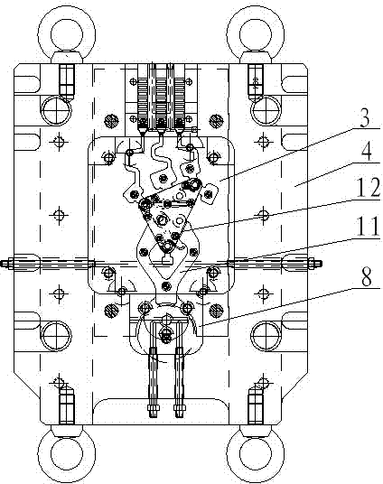
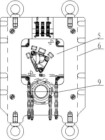
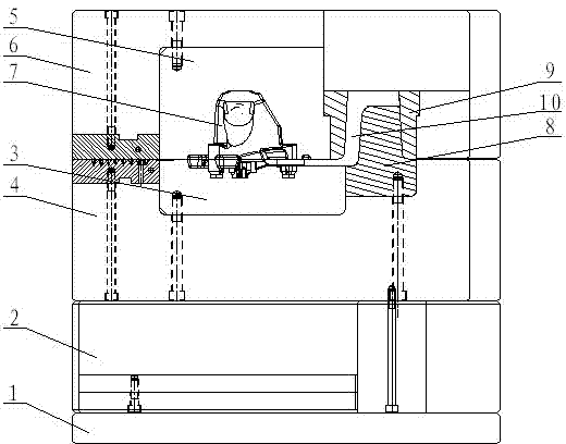
[0023] Embodiment 1: A die-casting and pouring method for the left suspension bracket of an engine, the die-casting and pouring method has the following steps:

[0024] 1) Install the mold on the die casting machine;

[0025] 2) Pour aluminum water into the melting cup material tube in the mold;

[0026] 3) Press the aluminum water in the melting cup tube through the sprue to the gate in the mold at a low speed by the hammer head of the die-casting machine;

[0027] 4) Press the hammer head forward at high speed, and press the aluminum water in the melting cup material tube into the mold cavity and slag bag;

[0028] 5) pressurize through the hammer to solidify the product in the cavity;

[0029] 6) Open the die-casting machine to demould the product;

[0030] 7) Remove the slag bag and sprue on the product.

[0031] Further, the pressure of the die-casting machine at low speed and high speed is 14MPa, the speed is 0.2m / s and 3m / s respectively, and the pressure is 28-33MPa...


PUM


Abstract

The invention discloses a die-casting pouring method for a left engine mounting bracket. The die-casting pouring method comprises the following steps that (1), a mold is installed to a die-casting machine; (2) molten aluminum is poured into a molten cup tube in the mold; (3) the molten aluminum in the molten cup tube is pressed to a pouring gate in the mold at a low speed through a runner via a hammer of the die-casting machine; (4) the hammer is pressed forwards at a high speed, so that the molten aluminum in the molten cup tube is pressed into a mold cavity and a cinder ladle; (5) pressurization is performed through the hammer, so that the product in the mold cavity is solidified; (6) the die-casting machine is turned on to de-molding the product; (7) the cinder ladle and the runner on the product are removed. The die-casting pouring method has the advantages that the process is stable, production speed is high, and yield is high; by the adoption of the method for the production of the left engine mounting bracket, product quality is guaranteed, product weight is reduced, and meanwhile the oil consumption of the whole vehicle is lowered; besides, production cost is also lowered.

Description

technical field [0001] The invention relates to a die-casting pouring method and a mold thereof, in particular to a die-casting pouring method and a mold thereof for an engine left suspension bracket. Background technique [0002] At present, the existing left engine mount bracket is produced by casting. Although this method can produce the product, the method still has the following deficiencies: 1. Since the left engine mount is produced by the casting method The process of the bracket is unstable, resulting in the quality of the product cannot be guaranteed. At the same time, the process makes the production speed slower, which directly affects the yield; 2. The left engine mount bracket produced by this casting method has a high cost; 3. Because the method uses molten iron for casting, the quality of the product is relatively heavy. After being installed on the automobile, the overall weight of the automobile is increased, and the fuel consumption of the automobile i...

Claims


Application Information

Patent Timeline
IPC IPC(8): B22D17/00B22D17/22
Inventor 罗勇
Owner CHONGQING DONGKE MOLD MFG
Why Eureka
Eureka Blog
Learn More