
Clamping and rotating mechanism of steel tube inner wall polishing device

A technology of rotating mechanism and internal polishing, applied in surface-polished machine tools, grinding/polishing equipment, grinding machine parts, etc. Stable, reasonable structure setting, good polishing effect

Inactive Publication Date: 2014-10-29
QINGDAO R & D INST XIAN JIAOTONG UNIV
View PDF6 Cites 4 Cited by
  • Summary
  • Abstract
  • Description
  • Claims
  • Application Information

AI Technical Summary

Problems solved by technology

Especially in recent years, with the promotion and popularization of pneumatic and hydraulic equipment, the steel pipes originally produced by cold rolling process in the industry can no longer meet the needs of customers
Under the demand of the market situation, most of the polishing process of the inner wall of the steel pipe is to install a polishing wheel on the output shaft of the motor. The labor intensity is high, the work efficiency is low, the product quality is not high, and the safety and reliability are low.
So on July 5, 2012, Huzhou Huading Stainless Steel Pipe Industry Co., Ltd. invented the patent name "Small Diameter Steel Pipe Internal Polishing Device", China Authorized Announcement No. CN 202622538 U. Although the patented technical solution can reduce labor intensity, its structural setting Unreasonable, the clamping and rotating mechanism is fixed, and the steel pipe is fed through the steel pipe feeding mechanism, so that the grinding head can polish the inner wall of the steel pipe. This technical scheme is easy to shake the steel pipe during processing, and it is difficult to ensure the processing quality. low efficiency

Method used


Image

  • Clamping and rotating mechanism of steel tube inner wall polishing device

Examples


Embodiment Construction

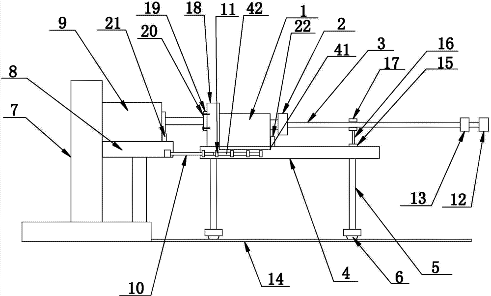
[0014] see figure 1 , a clamping and rotating mechanism of a steel pipe internal polishing device disclosed in the present invention includes a motor 1 and a three-jaw chuck 2 fixedly installed on the motor spindle, and a grinding rod 3 is inserted into the three-jaw chuck 2, so that The lower end of the motor 1 is provided with a motor base 4, the bottom of the motor base 4 is fixedly provided with four legs 5, and the bottom of each leg 5 is fixedly provided with a roller 6, and the upper end of the motor base 4 is provided with a motor mounting groove 41. The motor 1 is fixedly installed in the motor installation groove 41, the left end of the motor base 4 is provided with a cylinder base 7, and the right end surface of the cylinder base 7 is integrally provided with a support platform 8, and the cylinder 9 is fixedly installed on the support platform 8, The piston rod head of the cylinder 9 is detachably connected to the left end surface of the motor seat 4, and a transver...


PUM


Abstract

The invention discloses a camping and rotating mechanism of a steel tube inner wall polishing device. The camping and rotating mechanism comprises a motor, a three-jaw chuck and a grinding rod. A motor base is arranged at the lower end of the motor, four supporting feet are fixedly arranged at the bottom of the motor base, the bottom of each supporting foot is fixedly provided with a rolling wheel, an air cylinder base is arranged at the left end of the motor base, a supporting platform is integrally arranged on the right end face of the air cylinder base and fixedly provided with an air cylinder, the head portion of a piston rod of the air cylinder is detachably connected with the left end face of the motor base, transverse positioning grooves are symmetrically formed in the middle part of the front end face and the middle part of the rear end face of the motor base respectively, a positioning rod is arranged in each positioning groove, and a plurality of positioning blocks are fixedly arranged outside each positioning groove; a first grinding head used for rough machining is fixedly arranged at the right end of the grinding rod, and a second grinding head used for fine machining is fixedly arranged at the left end of the first grinding head. According to the technical scheme, a piston rod of the air cylinder stretches out and draws back to push the motor base to move leftwards and rightwards so that the grinding rod is driven to polish the inner wall of a steel tube, automated polishing is achieved, and the polishing effect is good.

Description

technical field [0001] The invention relates to the technical field of workpiece surface treatment devices, in particular to a clamping and rotating mechanism of a steel pipe inner polishing device. Background technique [0002] As customers have higher and higher requirements on the surface quality of steel pipes, as an intermediate manufacturer, it is also necessary to continuously improve the surface quality of steel pipes. Especially in recent years, with the promotion and popularization of pneumatic and hydraulic equipment, the steel pipes originally produced by cold rolling process in the industry can no longer meet the needs of customers. Under the demand of the market situation, most of the polishing process of the inner wall of the steel pipe is to install a polishing wheel on the output shaft of the motor. The labor intensity is relatively large, the work efficiency is low, the product quality is not high, and the safety and reliability are low. So on July 5, 201...

Claims


Application Information

Patent Timeline
IPC IPC(8): B24B41/04B24B29/08
CPCB24B29/08B24B41/06
Inventor 罗顺山高晞文杨飞
Owner QINGDAO R & D INST XIAN JIAOTONG UNIV
Features
  • Generate Ideas
  • Intellectual Property
  • Life Sciences
  • Materials
  • Tech Scout
  • Unparalleled Data Quality
  • Higher Quality Content
  • 60% Fewer Hallucinations
Learn More