Pressure reduction and vibration damping runner cone device

A technology of scupper cone and scupper hole, which is applied in the directions of hydropower generation, engine components, machines/engines, etc., can solve the problems of high thrust pad temperature, high pressure of the top cover, damage of the unit, etc., so as to improve the stress condition and reduce the Pressure pulsating, easy-to-process effects

Inactive Publication Date: 2014-10-29
HARBIN ELECTRIC MASCH CO LTD
View PDF5 Cites 16 Cited by
  • Summary
  • Abstract
  • Description
  • Claims
  • Application Information

AI Technical Summary

Problems solved by technology

Even with this structure, many power plants at home and abroad have problems of excessive roof pressure and hydraulic vibration to varying degrees after they are put into operation
In Liujiaxia and Dachaoshan hydropower stations, the pressure in the upper chamber of the runner was too high, which resulted in the temperature of the thrust tiles being too high. The hydropower stations in Sayang, Yantan and Wuqiangxi hydropower stations vibrated significantly, and even the units were damaged.

Method used


Image

  • Pressure reduction and vibration damping runner cone device
  • Pressure reduction and vibration damping runner cone device
  • Pressure reduction and vibration damping runner cone device

Examples


Embodiment 1

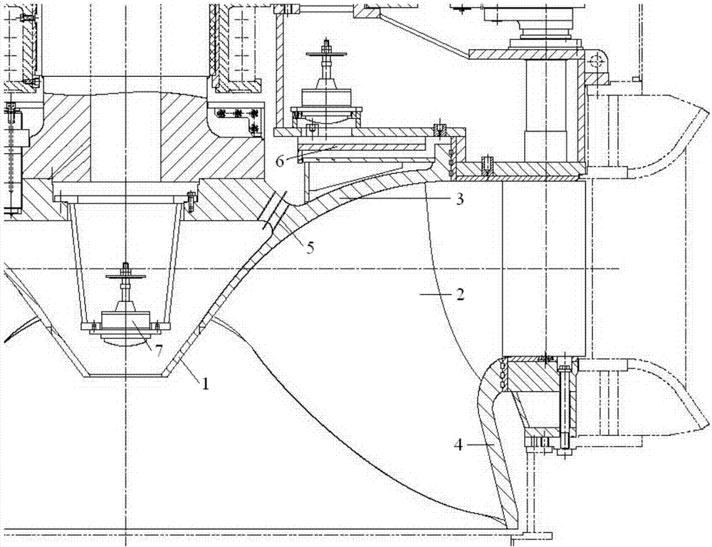
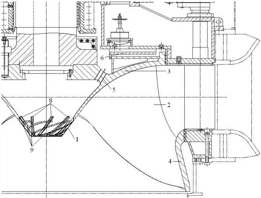
[0019] Such as figure 2 As shown, the decompression and damping water discharge cone device of the present invention includes a water discharge cone 1 connected to the upper crown 3 of the runner, the inside of the water discharge cone 1 is welded with uniformly distributed ribs 8, and the outside of the water discharge cone 1 There are evenly distributed spiral grooves 9 . The number of weep holes 5 is 14 evenly distributed, and the number of blades 2 is 13. The rotation direction of the unit is clockwise when viewed from the direction of the generator to the turbine.

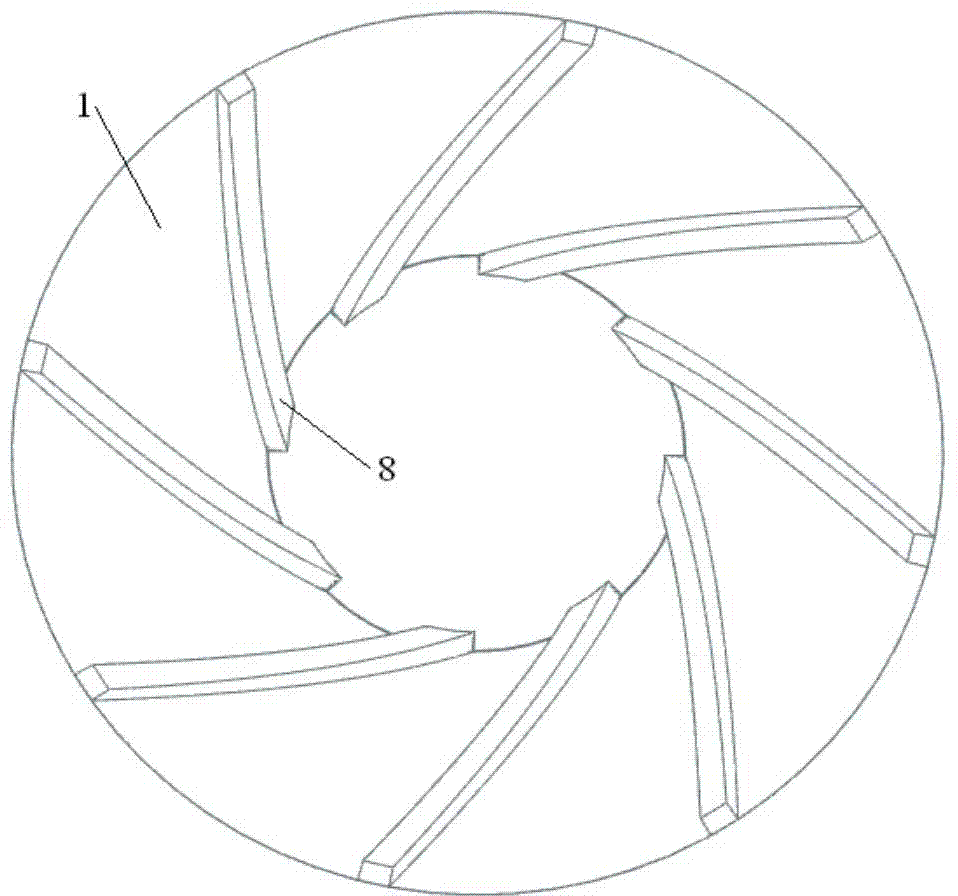
[0020] Such as image 3 As shown, the ribs 8 are inclined in the discharge cone 1, that is, they are inclined from the top of the discharge cone 1 to the bottom of the discharge cone 1 along the direction of rotation of the unit, and the inclination angle is 30° from the central axis of the runner. angle.

[0021] The ribs 8 are flush with the top and bottom of the drain cone 1, the width of the ribs 8 is...


PUM


Abstract

The invention relates to a pressure reduction and vibration damping runner cone device which comprises a runner cone (1) connected with a runner crown (3) of a rotary wheel, wherein a ribbed plate (8) is welded to the inner side of the runner cone (1), a spiral groove (9) is formed in the outer side of the runner cone (1), a water division plate (6) is arranged on a unit, and a drainage hole (5) is formed in the unit. When a mixed flow water turbine operates, the ribbed plate on the inner side of the runner cone pressurizes water flows drained out of the drainage hole, therefore, water drainage is increased, and axial hydraulic thrust of the unit is reduced; the spiral groove in the outer side of the runner cone drives the water flows close to the runner cone to rotate to smooth the water flows and perform water jet, pressure fluctuation of a draft tube is eliminated or weakened, and problems caused by hydraulic vibration are solved.

Description

technical field [0001] The invention relates to the technical field of Francis water turbines, in particular to a pressure-reducing, shock-absorbing, and water-discharging cone device. Background technique [0002] The Francis turbine is the most widely used. This type of unit has the advantages of compact structure, reliable operation, wide water head range and high efficiency at full load. However, many power plants at home and abroad have problems of high roof pressure and hydraulic vibration to varying degrees after they are put into operation. The top cover pressure equalizing pipe is added to connect the upper cavity of the top cover with the tail water, which can play a role of pressure relief. The power station adopts methods such as avoiding the operation in the vibration area and supplementing air to solve the problem of hydraulic vibration. However, some of these methods are limited by unit layout and complex structural forms, some cause serious energy waste, an...

Claims


Application Information

Patent Timeline
Patent Type & Authority Applications(China)
IPC IPC(8): F03B11/00F03B11/04
CPCY02E10/20
Inventor 李万王威张树邦高海军孔凡瑞
Owner HARBIN ELECTRIC MASCH CO LTD
Why Eureka
Try Eureka