Smooth high-speed centrifugal water injection pump

A high-speed, water-injection pump technology, applied in the field of centrifugal pumps, can solve the problems of sharp decline in corrosion resistance, high cost of replacing parts, and high cost of parts, so as to improve reliability and stability, reduce noise and vibration, and assemble Effect of Accuracy Improvement

Active Publication Date: 2017-08-25
ZHEJIANG KEER PUMP
View PDF7 Cites 0 Cited by
  • Summary
  • Abstract
  • Description
  • Claims
  • Application Information

AI Technical Summary

Problems solved by technology

[0003] The centrifugal pump operates under this working condition, and the existing centrifugal pump with a rotating speed of 2980r / min cannot meet its performance requirements, and the general stainless steel material cannot meet its corrosion resistance requirements.
If the centrifugal pump chooses the plunger pump, due to the high-speed continuous friction between the plunger valve and the pump cylinder during the operation of the plunger pump, the corrosion resistance of the pump cylinder and the valve body surface of the plunger valve will drop sharply, etc. , and cannot meet the corrosion resistance requirements for conveying high chloride ion content
Especially for such a large plunger pump, its noise and vibration will be much larger than that of ordinary centrifugal pumps, and it is difficult to guarantee the life of each friction pair
In addition, the plunger pump has many wearing parts. Even if it is in normal operation, the cost of replacing parts is very expensive. For the plunger pump made of duplex stainless steel, the cost of replacing parts is even greater.

Method used


Image

  • Smooth high-speed centrifugal water injection pump
  • Smooth high-speed centrifugal water injection pump
  • Smooth high-speed centrifugal water injection pump

Examples


Embodiment Construction

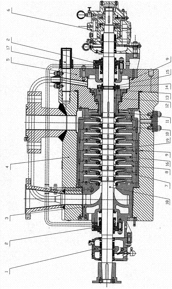
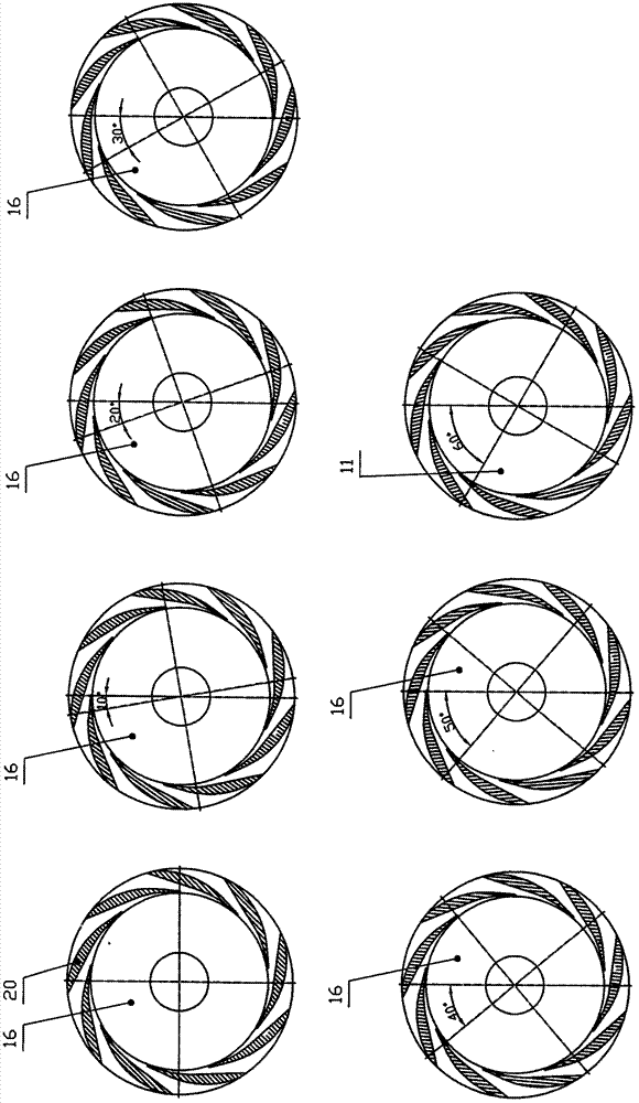
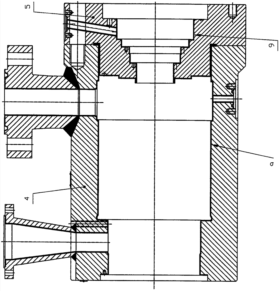
[0011] refer to Figure 1 to Figure 3 It can be seen that the smooth (small flow) high-speed centrifugal water injection pump of the present invention includes a pump cover 5, a housing assembly, a rotor assembly, a bearing assembly (including a left bearing assembly 1 and a right bearing assembly 6), and a mechanical seal assembly 2. The casing assembly includes a suction box body 3, a middle section 8, a final middle section 10, guide vanes 16 (several stages, except the last guide vanes) and a final guide vane 11 connected in sequence, the guide vanes 16, the final guide vanes The angle of the hydraulic inlet and outlet direction of the blade 11 is arranged in increments of 10° to 15° (set at a fixed numerical angle within this range) from the guide vane of the first stage to each stage of the guide vane of the last stage (such as figure 2 As shown, when the number of blades 20 on the guide vane 16 is nine pieces, it is one circle when it is rotated to a range of 30° in in...


PUM


Abstract

The invention discloses a stable high-speed centrifugal water injection pump, which includes a pump cover (5), a housing assembly, a rotor assembly, a bearing assembly, and a mechanical seal assembly (2). The housing assembly includes a suction box body that is connected in sequence. (3), the middle section (8), the middle section of the final stage (10), the guide vane (16) and the final stage guide vane (11). The hydraulic inlet and outlet direction angle of the guide vane and the final stage guide vane is from the first stage. Each stage from the guide vane to the final stage guide vane is arranged to rotate in increments of 10° to 15°. The invention can effectively balance the huge hydraulic impact thrown out by each guide vane in all directions, thereby greatly reducing the hydraulic impact caused by the pump operation and causing the pump to vibrate, effectively improving the reliability and stability of the pump and enabling the pump to be balanced. Efficient operation and reduced pump noise and vibration.

Description

technical field [0001] The invention relates to a centrifugal pump, in particular to a high-speed centrifugal water injection pump. Background technique [0002] In foreign-related oilfield projects, we often encounter problems with the selection of small flow and high-lift centrifugal water injection pumps, because foreign-related oilfields have the characteristics of small water injection volume, high water injection pressure, and contain a large amount of chloride ions and minerals. Especially for oil fields located in the deserts of the Middle East (such as Yada Oilfield in Iran), the rated water injection volume of a single well is 50m 3 / h, the outlet water pressure is 30MPa, and the chloride ion concentration can reach 165000mg / L. [0003] The centrifugal pump operates under this working condition, and the existing centrifugal pump with a rotating speed of 2980r / min cannot meet its performance requirements, and the general stainless steel material cannot meet its cor...

Claims


Application Information

Patent Timeline
Patent Type & Authority Patents(China)
IPC IPC(8): F04D1/06F04D29/42F04D29/44F04D29/22F04D29/66
Inventor 池庆杰沈水钦池武倪秀栋
Owner ZHEJIANG KEER PUMP
Why Eureka
Try Eureka