A rapid adjustment device for asymmetric hydrodynamic axial force of flywheel gap fluid

A hydrodynamic and asymmetric technology, applied in the field of fluid machinery, can solve the problems of time-consuming and laborious, increasing the number of installation and debugging of the test bench, and achieve the effect of optimizing the structure, simplifying the experimental adjustment plan, and controlling the hydrodynamic axial force.

Active Publication Date: 2017-06-13
SHANGHAI JIAO TONG UNIV
View PDF4 Cites 0 Cited by
  • Summary
  • Abstract
  • Description
  • Claims
  • Application Information

AI Technical Summary

Problems solved by technology

[0006] The purpose of the present invention is to provide a fast adjustment device for the asymmetrical hydrodynamic axial force of the flywheel gap fluid to solve the problem of the axial force in the optimization design of the existing large-scale shielded motor in order to study the flow state of the upper and lower end surfaces of the large-scale flywheel structure during operation. Therefore, it is necessary to verify the influence of the position adjustment of the return hole on the flow state of the flywheel lower end surface through experiments, and the severe nonlinear pressure distribution on the flywheel disk surface caused by the Ekman pump effect requires multiple sets of experiments to reflect the pressure distribution. Increase the number of installation and commissioning of the test bench, resulting in time-consuming and laborious technical problems in the design process

Method used


Image

  • A rapid adjustment device for asymmetric hydrodynamic axial force of flywheel gap fluid
  • A rapid adjustment device for asymmetric hydrodynamic axial force of flywheel gap fluid
  • A rapid adjustment device for asymmetric hydrodynamic axial force of flywheel gap fluid

Examples


Embodiment

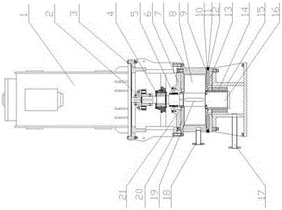
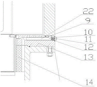
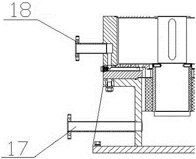
[0025] The flywheel 8 is fixed on the flywheel shaft 16 through the flywheel connecting key 19 and connected by the flywheel fastening nut 21 to form a flywheel rotor assembly. The flywheel rotor assembly is connected with the motor supporting base 3 and the flywheel supporting base 15 through the radial roller bearing 4 and the lower radial bearing 14 respectively. The flywheel casing 7 and the flywheel lower end cover 13 are connected to the flywheel support seat by bolts, the flywheel casing 7, the flywheel upper end cover 20 and the motor support seat connecting plate 6 are connected to the motor support seat 3, and the upper end of the flywheel shaft 16 is sealed with a mechanical seal 5, combined with The use of flywheel support seat 15 forms a closed gap flow channel. The driving motor 1 is connected with the motor support base 3, and connected with the flywheel shaft 16 through the flexible coupling 2, so as to drive the flywheel assembly to run. The return hole sleev...


PUM


Abstract

Disclosed is a flywheel gap fluid asymmetric hydrodynamic axial thrust quick adjustment device. The flywheel gap fluid asymmetric hydrodynamic axial thrust quick adjustment device comprises a dragging motor mounted on a motor support base, a flywheel rotor assembly mounted on a flywheel support base and a reflowing hole sleeve; the flywheel rotor assembly is connected with the dragging motor through a flexible coupler and comprises a flywheel lower cover arranged at the lower end, a reflowing hole sleeve mounting groove is formed in the flywheel lower cover, the reflowing hole sleeve is arranged in the reflowing hole sleeve mounting groove, a water inlet of the reflowing hole sleeve is connected with a water inlet flange tube, and a water outlet of the reflowing hole sleeve is connected with a water outlet flange tube. The reflowing hole sleeve mounting groove is formed in the flywheel lower cover of the adjustment device, so that the reflowing hole sleeve can be quickly mounted in or removed from the reflowing hole sleeve mounting groove; the adjustment device is designed in the embedment concept, and a reflowing hole position adjustment modular structure is additionally arranged on the base of large structural members, so that the change of the position of reflowing holes under the condition of no overall disassembly of a test bench is achieved.

Description

technical field [0001] The invention relates to the technical field of fluid machinery, in particular to a structural design for rapid adjustment of asymmetrical hydrodynamic axial force of large flywheel assemblies for some shielded motors. [0002] technical background [0003] With its technical advantages of no leakage, canned pumps are widely used in many industries such as energy and chemical industry. In a third-generation nuclear power technology, in order to improve the safety of the reactor, the shielded main pump is used as the core coolant circulation power source to replace the traditional shaft-sealed main pump. The introduction of the shielded main pump uses the design concept of pressure boundary conversion to improve the technical defect of the dynamic seal of the shaft-sealed main pump - the complete pressure boundary is used to replace the incomplete pressure boundary of the shaft-sealed pump, thereby improving the safety of the core . During the design p...

Claims


Application Information

Patent Timeline
Patent Type & Authority Patents(China)
IPC IPC(8): G01M10/00
Inventor 姚振强薛亚波成德徐正松沈洪王升德张磊华
Owner SHANGHAI JIAO TONG UNIV
Why Eureka
Try Eureka