Cooling cabinets for frequency converters

A frequency converter and cabinet technology, applied in the electrical field, can solve problems such as the lack of competitiveness of frequency converters, and the loss of reactors reduces the efficiency of frequency converters, and achieves the effects of simple structure, improved cooling effect, and improved cooling effect

Active Publication Date: 2017-05-17
CSR ZHUZHOU ELECTRIC LOCOMOTIVE RES INST
View PDF5 Cites 0 Cited by
  • Summary
  • Abstract
  • Description
  • Claims
  • Application Information

AI Technical Summary

Problems solved by technology

The increased loss of the reactor will reduce the efficiency of the inverter, making the inverter less competitive

Method used


Image

  • Cooling cabinets for frequency converters
  • Cooling cabinets for frequency converters
  • Cooling cabinets for frequency converters

Examples


Embodiment Construction

[0025] The present invention will be further described below in conjunction with accompanying drawing.

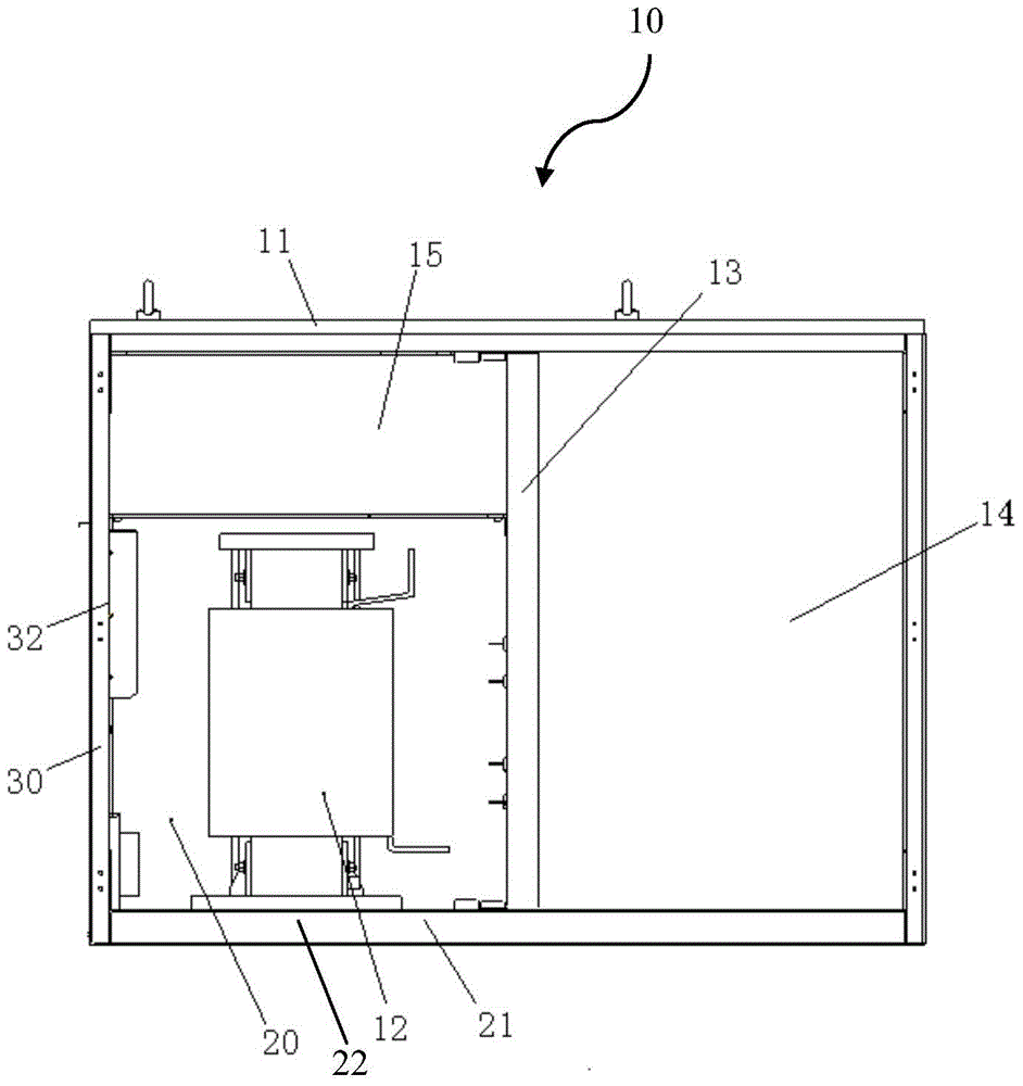
[0026] figure 1 A structural diagram of a cooling cabinet 10 for frequency converters (hereinafter simply referred to as the cabinet 10 ) according to the present invention is schematically shown. Such as figure 1 As shown, the cabinet 10 includes a bottom plate 21 , a side wall 30 and a top plate 11 . Viewed from the outside as a whole, the cabinet 10 is in the shape of a cuboid. A plurality of partitions 13 are arranged inside the cabinet 10 to divide the inside of the cabinet 10 into a plurality of cavities 20 , 14 , 15 . The components of the frequency converter are placed in these cavities, such as figure 1 The device 12 inside the cavity 20. Those skilled in the art will know that other devices are also arranged in the cavities 14 and 15. figure 1 not shown in It should be noted that each of these cavities includes a portion of the side wall 30 of the cabinet 1...


PUM


Abstract

The invention relates to a radiating cabinet for a frequency converter. A plurality of partition plates are arranged in the cabinet, the plurality of partition plates and corresponding areas of wall plates of the cabinet define a plurality of cavities for accommodating devices of the frequency converter, and the plurality of cavities are not communicated with one another. An air inlet area is arranged at the bottom of each cavity, and an air outlet area is arranged at the top of each cavity, so that air paths for blowing the devices of the frequency converter are formed in the cavities. According to the radiating cabinet for the frequency converter, the air paths for blowing the devices of the frequency converter are formed in the cabinet, so that effective radiating of the frequency converter can be achieved.

Description

technical field [0001] The invention relates to the electrical field, in particular to a cooling cabinet for a frequency converter. Background technique [0002] The frequency converter is used to convert the alternating current with constant voltage and frequency into alternating current with variable voltage or frequency, and it has a wide range of applications in fields such as motors. [0003] The frequency converter mainly includes high-voltage components and low-voltage components. High-voltage components include reactors, resistors and power devices, among which passive power devices such as reactors and resistors will generate a lot of heat when the inverter is running. On the one hand, too much heat accumulated in the cabinet of the inverter will significantly increase the temperature in the cabinet of the inverter, and excessive temperature will easily have a negative impact on other control components, affect the working stability of the inverter, and reduce the ...

Claims


Application Information

Patent Timeline
Patent Type & Authority Patents(China)
IPC IPC(8): H05K7/20
Inventor 李宇王婷刘海涛梁志伟黄敏刘雨欣从静姚大为杨林吴顶峰俞鹏程杨卓周命良卢程
Owner CSR ZHUZHOU ELECTRIC LOCOMOTIVE RES INST
Why Eureka
Try Eureka