Fluid system of flow cytometer and flow cell detecting method

A technology of flow cytometer and fluid system, applied in the field of flow cytometer fluid system and flow cytometry detection, can solve the problems of easily affected sample flow, high cost of flow cytometer, inconvenient maintenance, etc., so as to improve detection Accuracy, smooth sample flow, longevity effect

Active Publication Date: 2014-11-05
SHENZHEN DYMIND BIOTECH
View PDF7 Cites 17 Cited by
  • Summary
  • Abstract
  • Description
  • Claims
  • Application Information

AI Technical Summary

Problems solved by technology

[0014] In view of the above-mentioned deficiencies in the prior art, the purpose of the present invention is to provide a flow cytometer fluid system and a flow cytometr

Method used


Image

  • Fluid system of flow cytometer and flow cell detecting method
  • Fluid system of flow cytometer and flow cell detecting method
  • Fluid system of flow cytometer and flow cell detecting method

Examples


Embodiment 1

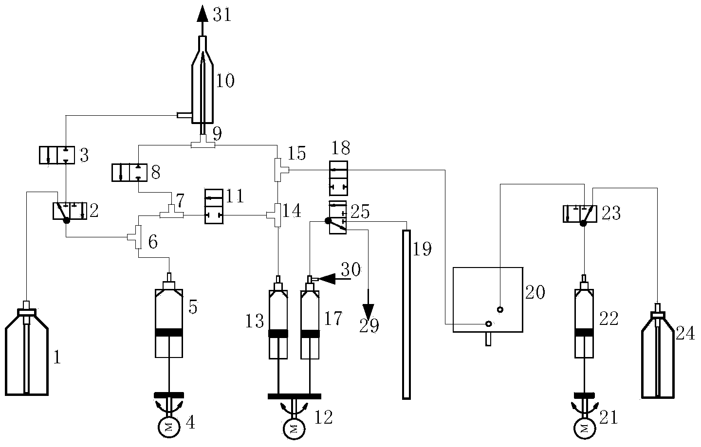
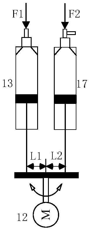
[0066] Such as Figure 4 As shown, the composition of a flow cytometer fluid system includes a sheath flow syringe 5, a sample flow syringe 13, a blood collection syringe 17, a hemolyzing agent syringe 22, a blood collection needle 19, a reaction pool 20, a flow chamber 10, a diluent barrel 1, Hemolytic agent bottle 24, first three-way valve 2, first two-way valve 3, second two-way valve 8, fourth two-way valve 18, second three-way valve 23, third three-way valve 25, first three-way valve Common joint 6, the 4th tee joint 14, the 5th tee joint 15 and each device are connected to each other used pipeline. 29 is the sampling needle cleaning inlet, 30 is the diluent inlet, and 31 is the flow chamber waste liquid outlet. Wherein, the sheath flow injector 5 is driven by the first motor 4 , the sample flow injector 13 and the blood collection injector 17 are driven by the second motor 12 , and the hemolytic agent injector 22 is driven by the third motor 21 . The sample flow inject...

Embodiment 2

[0075] Such as Figure 5 As shown, the composition of a flow cytometer fluid system includes a sheath flow injector 5, a sample flow injector 13, a blood collection injector 17, a hemolytic agent injector 22, a second hemolytic agent injector 26, a blood collection needle 19, a reaction pool 20, a flow Chamber 10, diluent barrel 1, hemolytic agent bottle 24, second hemolytic agent bottle 28, first three-way valve 2, first two-way valve 3, second two-way valve 8, fourth two-way valve 18, second two-way valve Two three-way valves 23, the third three-way valve 25, the fourth three-way valve 27, the first three-way joint 6, the fourth three-way joint 14, the fifth three-way joint 15 and the used pipelines connected to each other. 29 is the sampling needle cleaning inlet, 30 is the diluent inlet, and 31 is the flow chamber waste liquid outlet. Among them, the sheath flow injector 5 is driven by the first motor 4 , the sample flow injector 13 and the blood collection injector 17 ar...

Embodiment 3

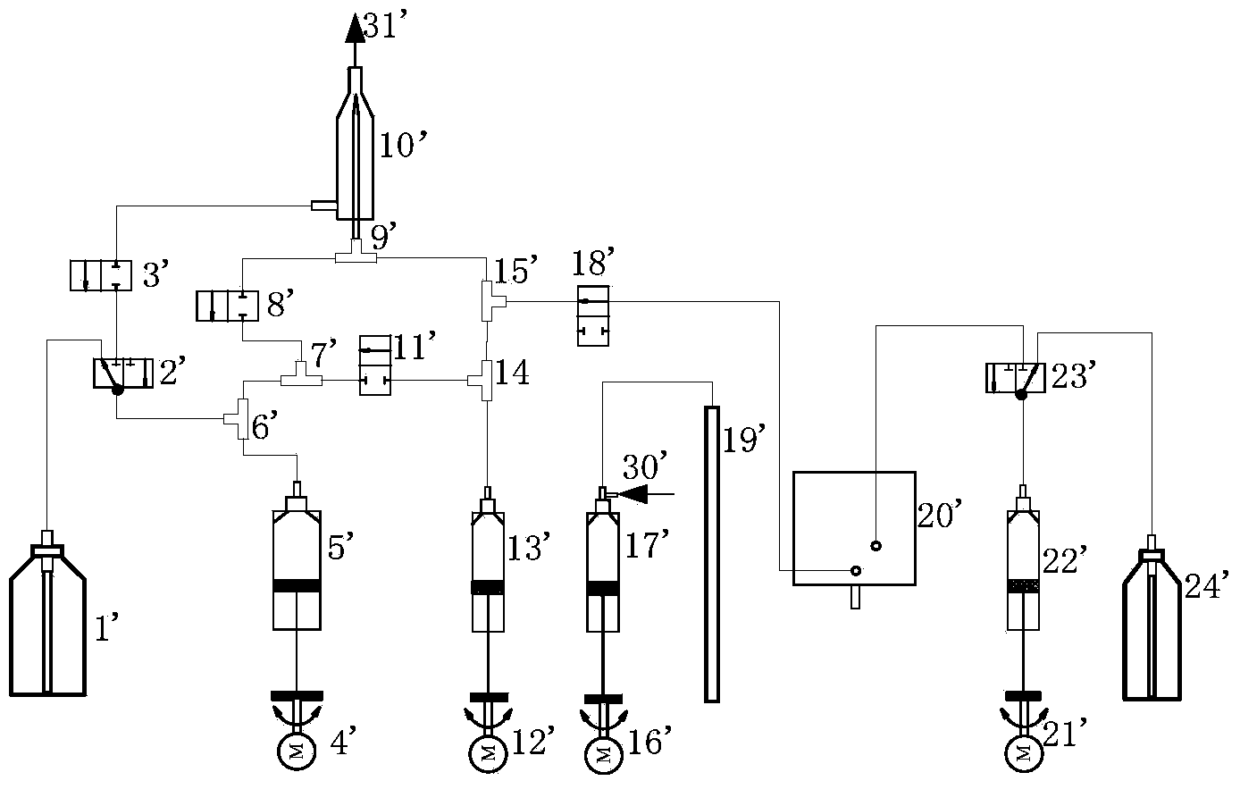
[0085] Such as Figure 6 As shown, the composition of a flow cytometer fluid system includes a sheath flow injector 5, a sample flow injector 13, a blood collection injector 17, a hemolytic agent injector 22, a second hemolytic agent injector 26, a blood collection needle 19, a reaction pool 20, a flow Chamber 10, diluent barrel 1, hemolytic agent bottle 24, second hemolytic agent bottle 28, first three-way valve 2, first two-way valve 3, second two-way valve 8, third two-way valve 11, second two-way valve Four two-way valve 18, second three-way valve 23, third three-way valve 25, fourth three-way valve 27, first three-way joint 6, second three-way joint 7, third three-way joint 9, fourth Three-way joint 14, the fifth three-way joint 15 and the pipelines used for connecting each device. 29 is the sampling needle cleaning inlet, 30 is the diluent inlet, and 31 is the flow chamber waste liquid outlet. Among them, the sheath flow injector 5 is driven by the first motor 4 , the ...


PUM


Abstract

The invention discloses a fluid system of a flow cytometer and a flow cell detecting method. The fluid system of the flow cytometer comprises a sheath flow injector, a sample flow injector, a blood sampling injector, a hemolytic agent injector, a blood sampling needle, a reaction tank, a flowing chamber, a diluent barrel, a hemolytic agent bottle, a first motor, a second motor and a third motor, wherein the sheath flow injector is driven by the first motor; the hemolytic agent injector is driven by the third motor; and the sample flow injector and the blood sampling injector are driven by the second motor. The sample flow injector and the blood sampling injector share the second motor, and are arranged in a moment balancing manner; the second motor is arranged between the two injectors; the cost of the system is reduced; the whole rigidity and the inertia of the system are also improved; sample flow is pushed by the injector stably; and the detection accuracy is improved.

Description

technical field [0001] The invention relates to the field of biomedical detection, in particular to a flow cytometer fluid system and a flow cytometry detection method. Background technique [0002] Flow cytometry is a blood analysis instrument that controls cells to pass through the detection area one by one through flow cytometry. Flow cytometry means that the cell flow (also called sample flow) is wrapped in the sheath fluid, and the cells line up through the flow chamber detection area. Advanced fluid control technology, which can avoid the problem of inaccurate detection caused by cells passing through the detection area according to irregular routes, and can greatly reduce the probability of missed detection caused by overlapping cells passing through the detection area. [0003] Existing flow cytometry is mainly divided into two categories. The first category is that both the sheath flow and the sample flow are pushed by a syringe. The second type is that the sample f...

Claims


Application Information

Patent Timeline
IPC IPC(8): A61B5/157G01N35/08
Inventor 刘治志
Owner SHENZHEN DYMIND BIOTECH
Why Eureka
Try Eureka