Medical bone fracture plate capable of being sustainably and initiatively pressurized and elastically fixed

A bone plate, active technology, applied in the direction of fixator, outer plate, internal bone synthesis, etc., can solve the problems of poor fracture union, screw breakage, high rigidity of bone plate, etc.

Inactive Publication Date: 2014-11-05
齐克海
View PDF5 Cites 2 Cited by
  • Summary
  • Abstract
  • Description
  • Claims
  • Application Information

AI Technical Summary

Problems solved by technology

However, the high rigidity of the bone plate causes the stress shielding of the proximal and distal fractures, which m

Method used


Image

  • Medical bone fracture plate capable of being sustainably and initiatively pressurized and elastically fixed

Examples


Embodiment Construction

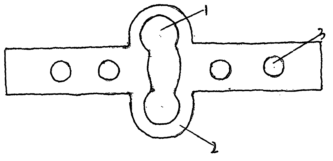
[0007] As shown in the figure, a hollow elastic hole (1) is designed in the middle of the existing bone plate, and the elastic hole (1) is deformed under the action of the pressurized screw hole (3) or the pressurizer, thereby producing an effect on the fracture near Active compression of the distal end. At the same time, the hollow design of the elastic hole (1) can achieve the effect of reducing stress shielding through deformation (especially when the bone plate is a locked bone plate). At the same time, in order to prevent the two wings of the bone plate from exceeding the edge of the bone and causing irritation to the body, it can be designed to surround the bone according to the bone shape of the specific fracture site (such as femur, tibia, fibula, humerus, ulna, radius, phalanx, etc.). Or semi-encircled structure. When the bone plate is made of memory alloy, the elastic hole (1) can be stretched and deformed toward the proximal and distal ends of the plate by placing ...


PUM


Abstract

The invention discloses a medical bone fracture plate capable of being sustainably and initiatively pressurized and elastically fixed. The middle of an existing bone fracture plate (usually a fracture portion to be fixed) is designed to be a hollow elastic hole (1), the elastic hole deforms under the action of pressurized screw holes (3) or a pressurizer, and near and far ends of the fracture can be initiatively pressurized. By the design of the hollow elastic hole (1), effect of stress shelter can be reduced by deformation of the elastic hole.

Description

technical field [0001] The invention relates to a surgical bone plate. Background technique [0002] Bone plate fixation is currently one of the main treatments for fractures. However, the high rigidity of the bone plate results in the shielding of the stress on the proximal and distal fractures, resulting in plate breakage, screw breakage and other adverse consequences, which is one of the main causes of poor fracture union and nonunion. At the same time, studies have shown that applying pressure to the fractured end can promote bone healing. Contents of the invention [0003] The purpose of the present invention is to realize active continuous pressurization and reduce the effect of stress shielding through the design of the elastic pressurization hole in the middle of the bone plate. [0004] Technical scheme of the present invention is as follows [0005] A hollow elastic hole (1) is designed in the middle of the existing bone plate (usually the fracture site to be ...

Claims


Application Information

Patent Timeline
IPC IPC(8): A61B17/80
CPCA61B17/8052
Inventor 齐克海
Owner 齐克海
Why Eureka
Try Eureka