
High pressure double-layer filtering device for steel rolling sludge treatment

A double-layer filtration and rolling sludge technology, which is applied in the direction of filtration separation, mobile filter element filter, separation method, etc., can solve the problems of affecting work efficiency, low work efficiency, and damage to the filter belt, so as to increase the filtering effect and improve The effect of enhancing work efficiency and firmness

Inactive Publication Date: 2014-11-05
佛山市高明和盈金属材料有限公司
View PDF8 Cites 2 Cited by
  • Summary
  • Abstract
  • Description
  • Claims
  • Application Information

AI Technical Summary

Problems solved by technology

In this process, the plate and frame filter press for processing the bottom sludge of the chemical degreaser has defects such as large equipment investment, large volume, complex mechanism, and intermittent operation due to structural reasons, resulting in low working efficiency and poor filtering effect.
Although the existing belt filter can realize continuous operation, it generally has defects such as easy blockage of the filter screen, high liquid content in the retentate, and unsatisfactory solid-liquid separation effect. In addition, because the filter working surface of the belt filter has A certain length, when the amount of material added to the filter belt is large, it is easy to cause damage to the filter belt. On the one hand, it limits the amount of material added to the filter, affecting work efficiency. On the other hand, it accelerates the wear of the filter belt and affects the service life of the belt filter.
At the same time, when the belt filter is filtering viscous and oily materials, single-layer filtration often cannot fully intercept some small oily solid particles, which will easily cause blockage of the filtrate collection device, seriously affecting the working efficiency of the filter and filtration. Effect

Method used


Image

  • High pressure double-layer filtering device for steel rolling sludge treatment
  • High pressure double-layer filtering device for steel rolling sludge treatment

Examples


Embodiment Construction

[0022] The present invention will be described in detail below in conjunction with the accompanying drawings, so that those of ordinary skill in the art can implement it after referring to this specification.

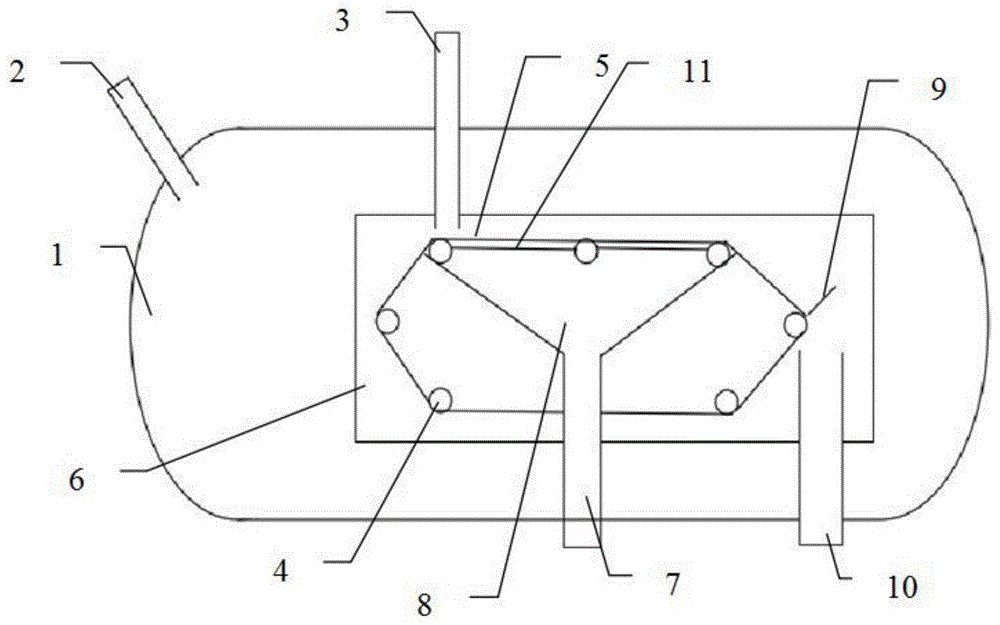
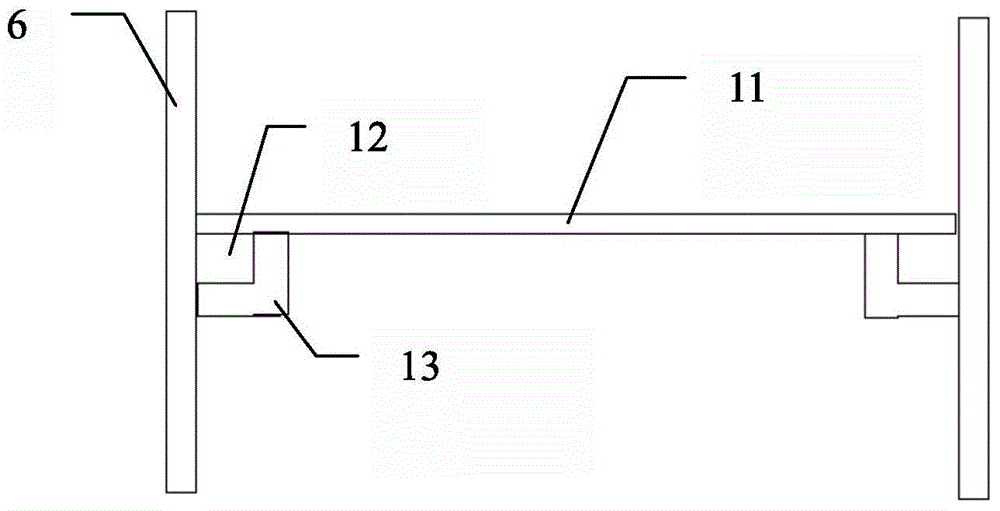
[0023] Such as Figure 1-2 As shown, a kind of high-pressure double-layer filter device for steel rolling sludge treatment according to the present invention comprises:

[0024] The sealed pressurized chamber 1 is a closed hollow tank, the wall of the sealed pressurized chamber 1 is provided with an air inlet pipe 2 and a feeding pipe 3, wherein the air inlet pipe 2 is connected with an air compressor to pressurize the airtight The chamber 1 is filled with high-pressure gas to form a high-pressure closed system, and the feeding pipe 3 is arranged on the upper part of the sealed pressurized chamber 1 for putting in the sludge to be treated.

[0025] A filter mechanism, which is arranged inside the sealed pressurized chamber 1, the filter mechanism includes a drive rolle...


PUM


Abstract

The invention discloses a high pressure double-layer filtering device for steel rolling sludge treatment. By disposing a plurality of demountable meshes in flexible connection with baffle plates between driving rollers on the upper surface of a filtering mechanism, and equipping the meshes with a small aperture, on the one hand, a strong supporting effect can be achieved on a filtering belt, the feeding amount per unit time is increased by over 10%, and on the other hand, an effective two-stage filtration effect can be realized on to-be-treated sludge so as to enhance the filtration effect, and clogging of a filtrate collecting device can be effectively avoided. At the same time, by adding a magnetic material capable of performing adsorption at flexible joints of the meshes and the baffle plates, the connection fastness of the meshes and the baffle plates is enhanced, and separation of the meshes from the baffle plates can be effectively avoided when the feeding amount on the filtering belt is great. In addition, by setting the filtrate collecting device as an inverted conical structure, adsorption of filtrate in the filtrate collecting device can be effectively reduced.

Description

technical field [0001] The invention relates to the field of steel rolling wastewater treatment, in particular to a high-pressure double-layer filter device for treating steel rolling sludge. Background technique [0002] Due to direct contact with the equipment, the circulating water of the steel rolling direct cooling system has a high content of suspended matter and oil in the water. At the same time, in the steel rolling process, a large amount of iron oxide washed down by the high-pressure water gun also enters the steel rolling direct cooling circulating cooling water system with water. Therefore, the steel rolling direct cooling circulating cooling water system is usually equipped with scale recovery and sludge treatment systems, generally including rolling mill swirl wells, chemical degreasers, mud pools and filter press systems. [0003] At present, in the traditional process of circulating water in the steel rolling direct cooling system, the bottom sludge of the c...

Claims


Application Information

Patent Timeline
IPC IPC(8): B01D33/35B01D33/04B01D33/056B01D33/46
Inventor 梁均全
Owner 佛山市高明和盈金属材料有限公司
Learn More