Supercharge Your Innovation With Domain-Expert AI Agents!

Method of selecting nitrogen springs for metal mold

A technology of nitrogen springs and molds, which is applied in the direction of forming tools, manufacturing tools, gas shock absorbers, etc., can solve the problems of large mold space, small initial force, and parts that cannot be lined up, so as to reduce production costs, smooth pressure changes, and The effect of taking up little space

Inactive Publication Date: 2014-11-05
WUZHOU HENGSHENG ELECTRONICS
View PDF6 Cites 0 Cited by
  • Summary
  • Abstract
  • Description
  • Claims
  • Application Information

AI Technical Summary

Problems solved by technology

[0002] In the industry of hardware mold development, elastic components have been widely used. In recent years, mold technology and mold manufacturing level have been greatly developed and improved. The demand for molds for industrial products is increasing, and molds are moving towards precision, The direction of complexity, high efficiency, and long life is developing rapidly, but the original conventional elastic elements have certain shortcomings, which cannot meet the needs of this situation, and cannot ideally solve the requirements of the stamping process, often affecting the quality of stamping parts and making the mold structure The design becomes more complicated, which affects the time for the mold to be replaced on the press; at the same time, the mold space occupied by conventional elastic elements is too large, which increases the cost of mold manufacturing
For example, springs and Uril glue all need to be pre-tightened to achieve the spring force required by the design, and their spring force increases significantly with the increase of the stroke. This kind of spring force is not constant, which may lead to Parts cannot be made, which is not ideal for drawing and blanking
For complex drawing forming parts, this contradiction is particularly prominent. In the prior art, the method of increasing the process has to be adopted to solve this kind of problem; for example, the initial force of spring and Youli glue is small, which is very important for the required initial force. Relatively large bending, flanging and other processes are not ideal; and the resulting result is directly: the quality of stamping parts is unstable, and it takes time and effort to adjust the mold
At the same time, for thick plate fine-blanking blanking process, if using spring or unglue to unload, it often encounters that the unloading space of the mold is not enough to place the spring or unglue, and it is necessary to increase the mold space to solve the problem

Method used


Image

  • Method of selecting nitrogen springs for metal mold

Examples


Embodiment Construction

[0018] The invention will be further described in detail below in conjunction with the accompanying drawings and specific embodiments.

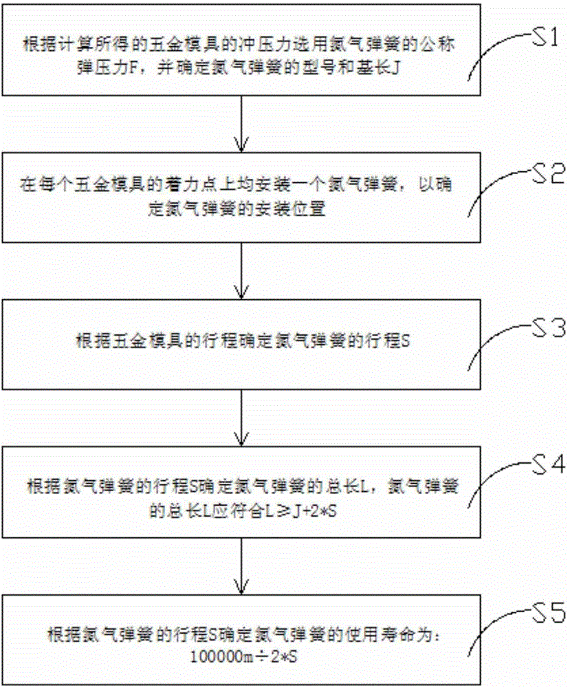
[0019] refer to figure 1 As shown, the present invention provides a method for selecting a nitrogen spring in a metal mold, the method comprising the following steps:

[0020] The first step is to select the nominal elastic force F of the nitrogen spring according to the stamping force of the metal mold obtained from the calculation, and determine the model and base length J of the nitrogen spring; because after the mold is worn, there will be gap changes, the cutting edge will become blunt and other processes The change of parameters, the inconsistency of the mold thickness and the deformation resistance of the mold plate will cause the change of the deformation resistance of the workpiece, so there should be room for the deformation resistance in the design. When the nitrogen spring is inflated, the high-pressure gas will inevitably have th...


PUM


Abstract

The invention relates to the technical field of molds and discloses a method of selecting nitrogen springs for a metal mold. The method includes steps of S1, selecting the nominal spring force F of the nitrogen springs according to calculated stamping force of the metal mold and determining model and basic length of the nitrogen springs; S2, installing one nitrogen spring to each point of strength of the metal mold to determine installation position of the nitrogen springs; S3, determining travel S of each nitrogen spring according to travel of the metal mold; S4, determining the total length L of each nitrogen spring according to the travel S of the nitrogen spring; and S5, determining service life of the nitrogen spring to be 100000m / 2*S according to the travel S of the nitrogen spring. The total length of the nitrogen spring should meet the relational expression L> / =J+2*S. The whole mold with the nitrogen springs selected and installed by the method has the advantages of small space occupation, high elasticity, easy and stable pressure variation and capability of improving workpiece stamping quality and reducing production cost.

Description

technical field [0001] The invention relates to the technical field of moulds, and more specifically relates to a method for selecting nitrogen springs in hardware moulds. Background technique [0002] In the industry of hardware mold development, elastic components have been widely used. In recent years, mold technology and mold manufacturing level have been greatly developed and improved. The demand for molds for industrial products is increasing, and molds are moving towards precision, The direction of complexity, high efficiency, and long life is developing rapidly, but the original conventional elastic elements have certain shortcomings, which cannot meet the needs of this situation, and cannot ideally solve the requirements of the stamping process, often affecting the quality of stamping parts and making the mold structure The design becomes more complicated, which affects the time for the mold to be replaced on the press; at the same time, the mold space occupied by c...

Claims


Application Information

Patent Timeline
IPC IPC(8): B21D37/12F16F9/02
Inventor 宋云
Owner WUZHOU HENGSHENG ELECTRONICS
Features
  • R&D
  • Intellectual Property
  • Life Sciences
  • Materials
  • Tech Scout
  • Unparalleled Data Quality
  • Higher Quality Content
  • 60% Fewer Hallucinations
Learn More