External gas assisted injection mould

An injection mold and external gas technology, applied in the field of external gas-assisted injection molds, can solve the problems of carbonization of injection parts, bubbles of injection parts, gas leakage, etc., to achieve good exhaust effect, ensure injection quality, and facilitate processing.

Inactive Publication Date: 2014-11-05
ZHEJIANG UNIV OF TECH
View PDF4 Cites 23 Cited by
  • Summary
  • Abstract
  • Description
  • Claims
  • Application Information

AI Technical Summary

Problems solved by technology

In the process of external gas-assisted injection molding, gas is injected between the melt and the mold wall for pressure-holding cooling, but in most cases, gas may leak from the vent grooves, parting surfaces and other parts of the mold, resulting in pressure loss
In order to ensure that there is no gas leakage, it is necessary to consider the problem of preventing the leakage of the holding gas when designing the external gas-assisted injection mold. When the melt fills the cavity, the air in the cavity must be smoothly discharged. If the gas in the cavity If it cannot be discharged in time, defects such as air bubbles, seams or lack of material will be formed on the molded injection molded parts, and in severe cases, it may even cause local carbonization and burning of the injection molded parts

Method used


Image

  • External gas assisted injection mould
  • External gas assisted injection mould

Examples


Embodiment Construction

[0019] The present invention will be further described below in conjunction with the accompanying drawings and specific embodiments.

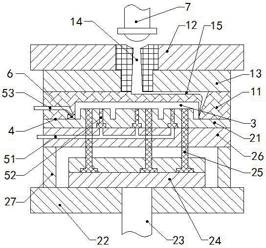
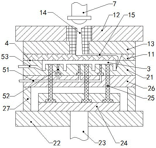
[0020] like figure 1 and figure 2 , are structural schematic diagrams of two embodiments of the present invention.

[0021] The external gas-assisted injection mold provided by the embodiment of the present invention includes an upper mold 11 and a lower mold 21 that cooperate with each other, and a cavity 3 with the same shape as the injection molded part is arranged between the upper mold and the lower mold, and the upper mold and the lower mold The contact surface between them is the parting surface 4 of the mould. The parting surface should be arranged at the corner or the outer surface of the injection molded part, and the upper mold and the lower mold are sealed at the parting surface.

[0022] like figure 1 As shown, the parting surface 3 in the first embodiment is bent, the peripheral edge of the parting surface is flush with the lo...


PUM


Abstract

The invention provides an external gas assisted injection mould, and relates to the technical field of injection mould. The injection mould comprises an upper mould and a lower mould which cooperate with each other. A cavity having the same shape as an injection moulding is cooperatively arranged between the upper mould and the lower mould. The surface where the upper mould and the lower mould contact is the mould joint. The injection mould is characterized in that: the upper mould and the lower mould are respectively cooperatively provided with an air inlet duct and an air outlet duct; one end of the air inlet duct is connected to a gas pipe, the other end of the air inlet duct is communicated with the cavity through evenly arranged gas pins; one end of the air outlet duct is connected to the cavity, and the other end of the air outlet duct is communicated with the external space. The provided external gas assisted injection mould has a simple structure, is convenient for processing, can effectively solve the problem of gas sealing between the injection moulding and the surface of the mould joint during the pressure maintaining process of an external assistant gas, and is capable of maintaining the gas sealing during the pressure maintaining process and achieving a very good gas discharging effect during the injection mould filling process. The injection moulding quality of injection moulding is guaranteed, and the injection moulding is easy to demould.

Description

technical field [0001] The invention relates to the technical field of injection molds, in particular to an external air-assisted injection mold. Background technique [0002] Gas-assisted injection molding technology is an emerging injection molding technology, including internal gas-assisted injection molding and external gas-assisted molding. Internal gas-assisted molding is to inject gas into the melt, and external gas-assisted molding is to inject gas between the melt and the mold wall after the melt fills the cavity. [0003] During the cooling process of external gas-assisted injection molding, the gas pressure compensates the shrinkage of the plastic, which can effectively reduce or even eliminate the possible dents on the back of the rib. In the process of external gas-assisted injection molding, gas is injected between the melt and the mold wall for pressure-holding cooling, but in most cases, gas may leak from the vent grooves, parting surfaces and other ...

Claims


Application Information

Patent Timeline
Patent Type & Authority Applications(China)
IPC IPC(8): B29C45/26B29C45/34B29C45/40
CPCB29C45/174B29C2045/1741B29C45/34B29C45/1711B29C2045/4015
Inventor 姜少飞李吉泉徐伏宇
Owner ZHEJIANG UNIV OF TECH
Why Eureka
Try Eureka