Forced-cooling high-power LED lamp

A technology of LED lamps and high power, which is applied to lighting and heating equipment, cooling/heating devices of lighting devices, lighting devices, etc. The effect of power consumption and efficient heat dissipation

Active Publication Date: 2014-11-05
天津朝辉照明科技有限公司
View PDF9 Cites 4 Cited by
  • Summary
  • Abstract
  • Description
  • Claims
  • Application Information

AI Technical Summary

Problems solved by technology

Theoretical verification and a large number of example projects prove that the use of natural heat dissipation cannot solve the problem of light decay of high-power LED lamps, and it is necessary to find another way to break through this technical bottleneck

Method used


Image

  • Forced-cooling high-power LED lamp
  • Forced-cooling high-power LED lamp
  • Forced-cooling high-power LED lamp

Examples


Embodiment l

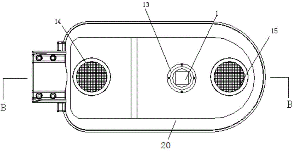
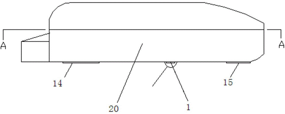
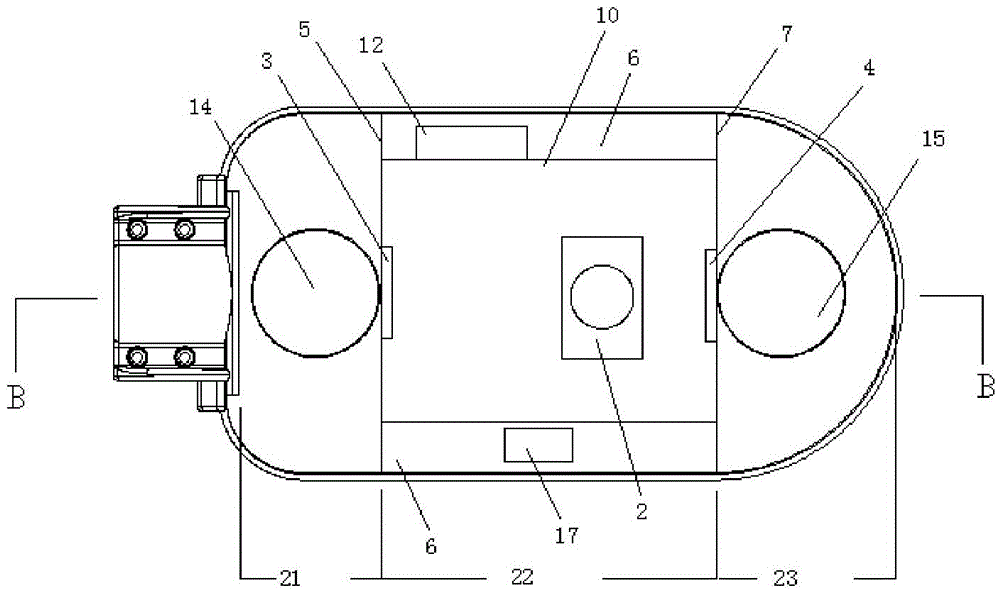
[0055] 100W rainproof LED street light for single fin heat pipe radiator, according to Picture 1-1 , Figure 1-2 , Figure 1-3 , Figure 1-4 , Figure 1-5 shown.

[0056] A forced heat dissipation high-power LED lamp, comprising a lamp housing 20, an air intake area 21, a heat dissipation area 22, and an exhaust area 23, the air intake area 21, the heat dissipation area 22, and the exhaust area 23 are assembled in the lamp housing 20; An air inlet partition 5 is provided between the area 21 and the heat dissipation area 22, and the air inlet partition 5 is provided with an air inlet partition air guide hole 8; an exhaust partition is provided between the heat dissipation area 21 and the exhaust area 23 7. The air exhaust partition 7 is provided with the air guide hole 9 of the exhaust partition; the air intake area 21 includes the air intake fan 3, the air intake hole 14 of the lamp housing, the overflow hole 11, the rain blocking plate 16, the insect net 24 and the resist...

Embodiment 2

[0060] For parallel connection of 2 fin radiators 200W rainproof LED street light, according to diagram 2-1 , Figure 2-2 , Figure 2-3 , Figure 2-4 , Figure 2-5 shown.

[0061] The difference from Embodiment 1 is that the cross section of the air duct 10 is circular;

[0062] The air duct 10, the air inlet partition 5, the exhaust partition 7, the inlet fan 3, the exhaust wind 4, and the outer surface of the finned heat pipe radiator 2 all have a nano-ceramic non-stick coating layer;

[0063] Air duct 10 adopts copper plate to make.

[0064] The air intake fan 3 is installed on the outside of the air intake partition 5 of the air duct 10; the exhaust fan 4 is installed on the outside of the exhaust partition 7 of the air duct 10;

[0065] The finned heat pipe radiators 2 are connected in parallel in the lamp housing 20 , and each finned heat pipe radiator 2 is independent of each other.

Embodiment 3

[0067] For 2 fin radiators connected in series 200W rainproof LED street light, according to Figure 3-1 , Figure 3-2 , Figure 3-3 , Figure 3-4 , Figure 3-5 shown.

[0068] The difference from Embodiment 1 is that the cross section of the air duct 10 is circular;

[0069] Air duct 10, air intake partition 5, exhaust partition 7, intake fan 3, exhaust air 4, and finned heat pipe radiator 2 are all provided with polytetrafluoroethylene non-stick coating layer on the outer surface

[0070] Air duct 10 adopts iron plate to make.

[0071] The finned heat pipe radiators 2 are connected in series in the lamp housing 20 , and each finned heat pipe radiator 2 is independent of each other.


PUM


Abstract

The invention relates to LED illumination lamps, in particular to a forced-cooling high-power LED lamp. The forced-cooling high-power LED lamp comprises a lamp shell, an air inlet area, a heat dissipation area and an air exhaust area, and the air inlet area, the heat dissipation area and the air exhaust area are assembled in the lamp shell. An air inlet separation plate is arranged between the air inlet area and the heat dissipation area, and air inlet separation plate air guide holes are formed in the air inlet separation plate. An air exhaust separation plate is arranged between the heat dissipation area and the air exhaust area, and air exhaust separation plate air guide holes are formed in the air exhaust separation plate. The forced-cooling high-power LED lamp has the advantages of being high in power, light, high in light efficiency, low in junction temperature, high in energy efficiency, low in cost, free of maintenance and capable of being intelligently controlled.

Description

technical field [0001] The invention relates to an LED lighting lamp, in particular to a forced heat dissipation high-power LED lamp. Background technique [0002] LED has the characteristics of unidirectional light emission, low power consumption, and long life, and is the most promising alternative light source for road lighting or other gas light sources. Traditional gas lights due to 360 0 Luminous, resulting in more than 50% of energy waste. If the maturity of LED street lamps can reach the technical level of traditional high-pressure sodium lamps, using equal-illuminance LED street lamps to replace high-pressure sodium lamps will save electricity by more than 60%, and the economic benefits are very significant. [0003] The electricity-to-light conversion rate of LED is about 25%, and the remaining electricity is converted into heat energy. If the heat cannot be conducted out at an extremely fast speed, it will cause the junction temperature to be too high and cause...

Claims


Application Information

Patent Timeline
Patent Type & Authority Applications(China)
IPC IPC(8): F21S2/00F21V29/02F21V23/00F21V33/00F21Y101/02
Inventor 付洪斌
Owner 天津朝辉照明科技有限公司
Why Eureka
Try Eureka