
Energy-saving fuel system for thermal power plant

A technology of fuel oil system and thermal power plant, which is applied in the direction of combustion method, liquid fuel supply/distribution, etc. It can solve the problems of exceeding the flash point, waste of energy consumption, rise of oil temperature, etc., and achieve the effect of saving energy and stabilizing oil pressure

Inactive Publication Date: 2014-11-05
HENAN AOKE POWER TECH CO LTD
View PDF5 Cites 5 Cited by
  • Summary
  • Abstract
  • Description
  • Claims
  • Application Information

AI Technical Summary

Problems solved by technology

[0003] The purpose of the present invention is to provide an energy-saving fuel oil system in a thermal power plant, which is used to solve the problems of waste of energy consumption and increase of oil temperature beyond the flash point caused by the oil supply pump of the fuel oil system still needing to rotate for standby when the boiler combustion is stable

Method used


Image

  • Energy-saving fuel system for thermal power plant

Examples


Embodiment Construction

[0014] The present invention will be described in further detail below in conjunction with the accompanying drawings.

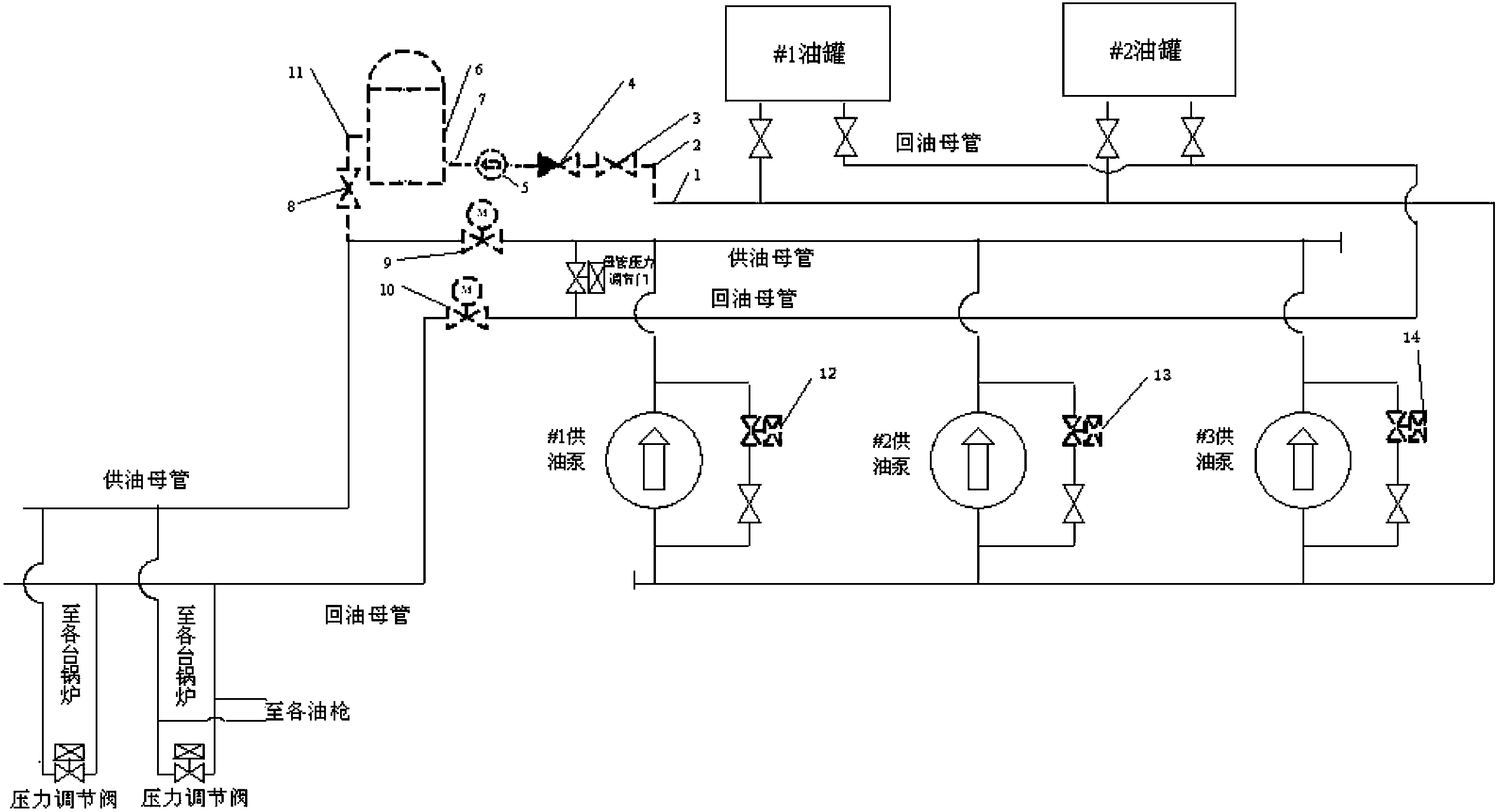
[0015] An energy-saving fuel system for a thermal power plant introduced by the present invention includes an oil tank, an oil supply pump, an oil gun, and an oil supply main pipe and an oil return main pipe of the oil gun, between the outlet of the oil tank and the oil supply main pipe of the oil gun The oil circuit pressurizing device is connected between them, the first regulating valve is arranged on the pipeline between the oil outlet of the oil supply pump and the oil outlet of the oil circuit pressurizing device, and the second regulating valve is arranged on the oil return main pipe , the oil pressure device includes a fuel storage tank and a fuel pressure pump.

[0016] Specific implementation methods such as figure 1 As shown, 1 is the end of the oil supply main pipe at the outlet of the oil tank; 2 is the stainless steel pipe; 3 and 8 are manual v...


PUM


Abstract

The invention relates to an energy-saving fuel system for a thermal power plant. The energy-saving fuel system comprises fuel tanks, fuel supply pumps, a fuel gun and a fuel supply mains and a fuel return mains of the fuel gun. A fuel channel pressurizing device is connected between outlets of the fuel tanks and the fuel supply mains, a first adjusting valve is arranged on a pipeline between fuel outlet ends of the fuel supply pumps and a fuel outlet end of the oil channel pressurizing device, the fuel return mains is provided with a second adjusting valve, and the fuel channel pressurizing device comprises a fuel energy storage tank and a fuel pressure pump. The fuel system for the thermal power plant keeps fuel pressure stable on the premise of no spinning reserve of the fuel supply pump, energy resources are saved, and the problem that fuel temperature rises to exceed flammability point is avoided.

Description

technical field [0001] The invention relates to an energy-saving fuel oil system in a thermal power plant. Background technique [0002] The fuel oil system of coal-fired thermal power plants is used for boiler ignition and stable combustion. The current problem is that the fuel system still needs to maintain normal operation when the boiler is burning stably and does not need oil to support combustion, so as to deal with the unstable combustion that may occur at any time. The long-term operation of the fuel supply pump in the fuel system will cause a lot of useless energy consumption. The useless energy consumption will be dissipated in the form of heat, which will make the fuel supply pump heat up and eventually cause the temperature of the fuel to rise, especially in summer when the oil temperature often exceeds #0. point, the risk increases significantly. Contents of the invention [0003] The purpose of the present invention is to provide an energy-saving fuel oil s...

Claims


Application Information

Patent Timeline
IPC IPC(8): F23K5/04
Inventor 胡优美
Owner HENAN AOKE POWER TECH CO LTD
Learn More