Pneumatic shearing machine
A technology for shearing machines and air compressors, which is applied in the direction of shearing devices, shearing machine equipment, and accessories of shearing machines. It can solve the problems of affecting the shearing effect and reducing the service life of equipment, so as to ensure the shearing effect Effects of improving cleanliness and extending service life
- Summary
- Abstract
- Description
- Claims
- Application Information
AI Technical Summary
Problems solved by technology
Method used
Image

Examples
Embodiment Construction
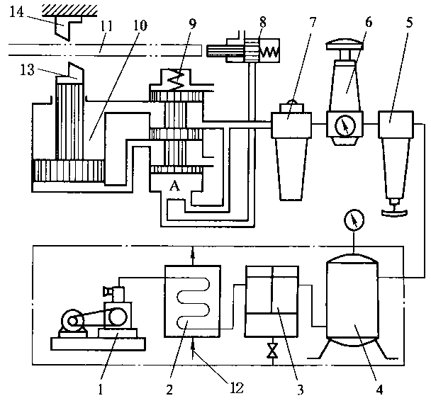
[0012] The technical scheme of the present invention will be described in further detail below in conjunction with the accompanying drawings and specific embodiments, so that those skilled in the art can better understand the present invention and implement it, but the examples given are not intended to limit the present invention.
[0013] Such as figure 1 As shown, a pneumatic shearing machine includes an air compressor 1, an air storage tank 4, and a motorized reversing valve 8. The motorized reversing valve 8 is also called a stroke valve, which is mainly used to control the stroke of mechanical moving parts, and can also be used as a safety valve. figure 1 The middle is a two-position motorized reversing valve 8, the right side of the motorized reversing valve 8 is provided with a return spring, and the left end is provided with a push rod. Inlet at the bottom of valve 9.
[0014] A water cooling device 2 and an oil remover 3 are sequentially arranged between the air co...
PUM
 Abstract
Description
Claims
Application Information
 - Generate Ideas
- Intellectual Property
- Life Sciences
- Materials
- Tech Scout
- Unparalleled Data Quality
- Higher Quality Content
- 60% Fewer Hallucinations
Browse by: Latest US Patents, China's latest patents, Technical Efficacy Thesaurus, Application Domain, Technology Topic, Popular Technical Reports.
© 2025 PatSnap. All rights reserved.Legal|Privacy policy|Modern Slavery Act Transparency Statement|Sitemap|About US| Contact US: help@patsnap.com