
Lens injection molding mould and injection molding method

A technology of injection mold and lens, which is applied to other household appliances, optical components, household appliances, etc., can solve the problems of low production efficiency, short cooling time, and long cooling time, and achieve simple and practical structure, short cooling time, and high production efficiency. high effect

Active Publication Date: 2014-11-12
宁波雷邦机械科技有限公司
View PDF4 Cites 2 Cited by
  • Summary
  • Abstract
  • Description
  • Claims
  • Application Information

AI Technical Summary

Problems solved by technology

[0003] The purpose of the present invention is to overcome defects such as shrinkage cavities, air bubbles and deformation after demoulding due to large stress and long cooling time after injection molding to overcome the current traditional injection mold and injection molding method for injection molding lenses with a certain thickness. Low deficiency, providing a lens injection mold and injection molding method that is not easy to produce shrinkage cavity, air bubbles and deformation after demolding during injection molding, and has short cooling time after injection molding and high production efficiency

Method used


Image

  • Lens injection molding mould and injection molding method
  • Lens injection molding mould and injection molding method
  • Lens injection molding mould and injection molding method

Examples


Embodiment Construction

[0015] The present invention will be further described below in conjunction with the accompanying drawings.

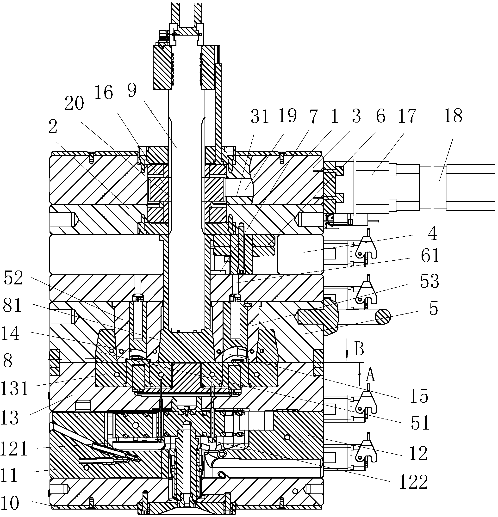
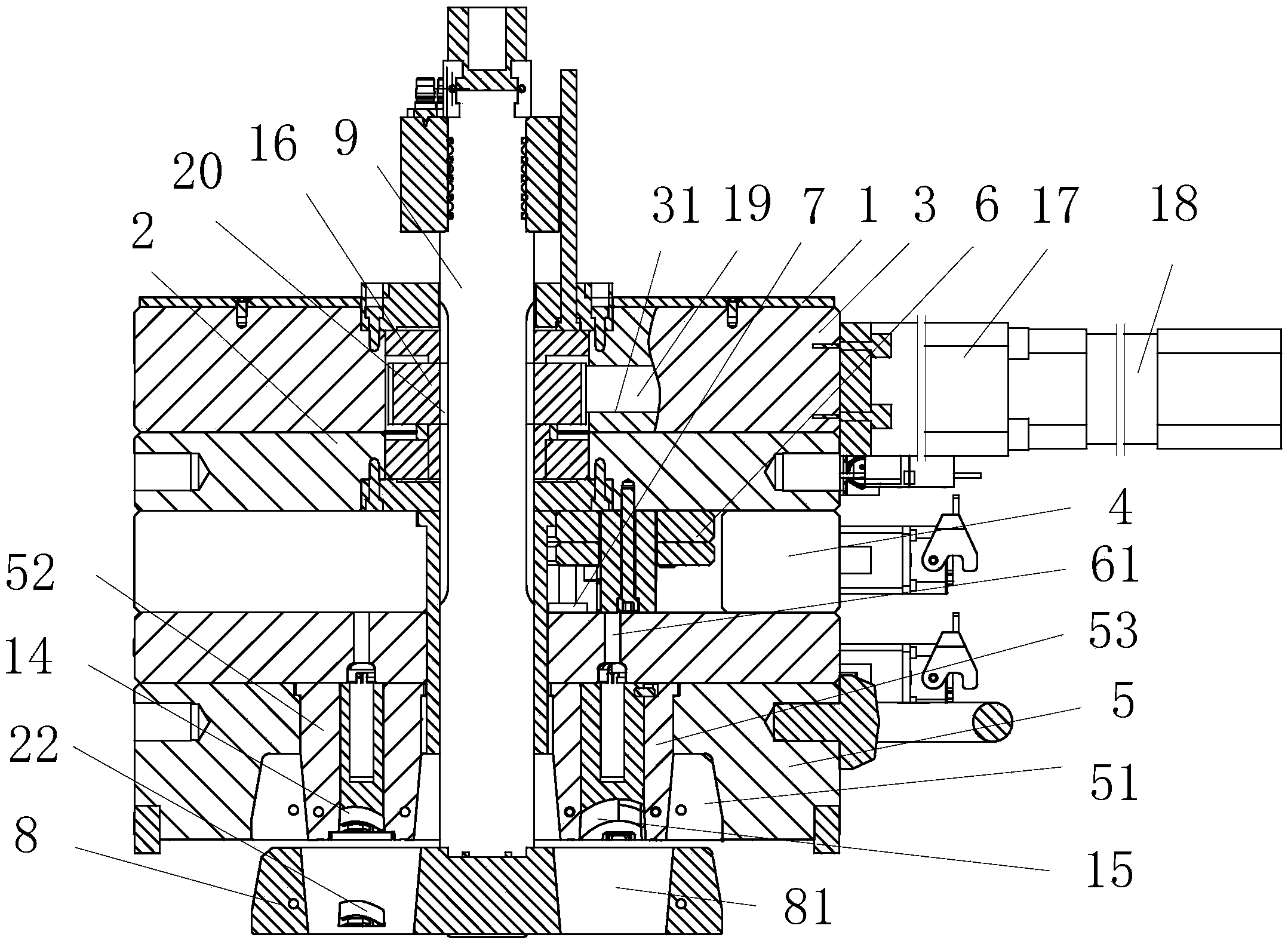
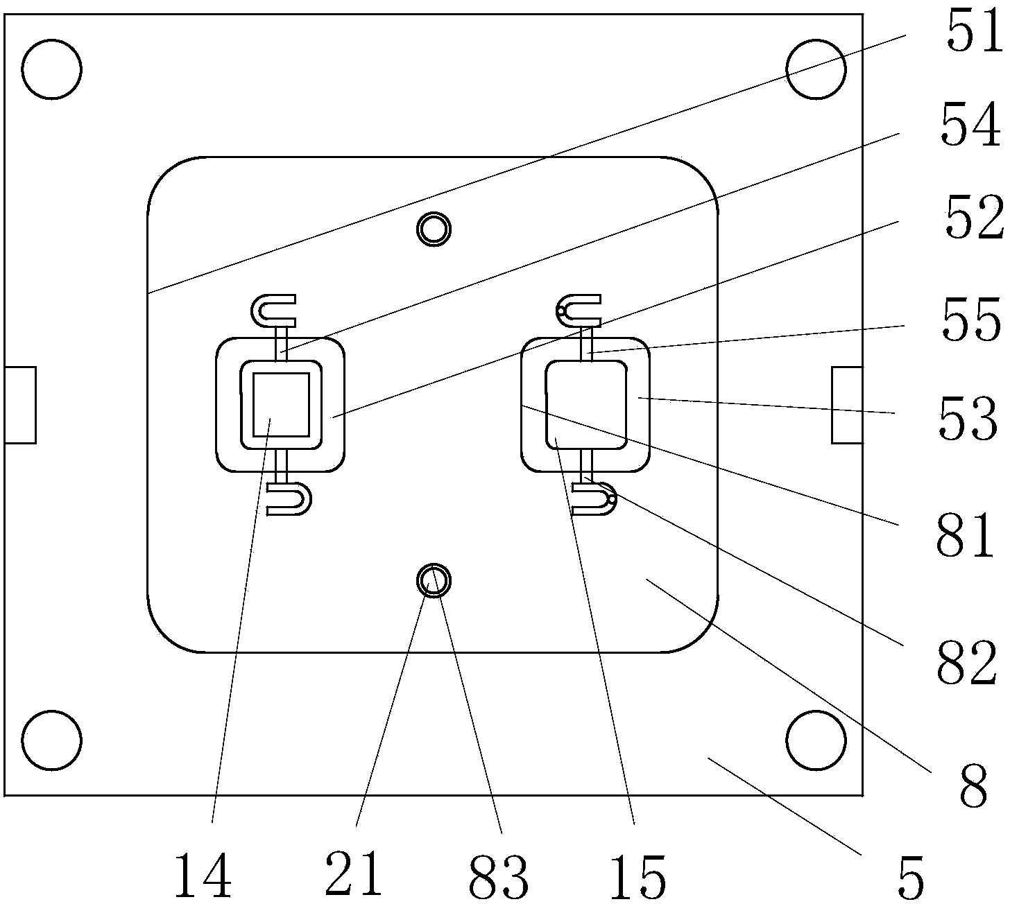
[0016] as attached figure 1 , attached figure 2 , attached image 3 , attached Figure 4 Shown: a lens injection mold, including a movable mold and a fixed mold; the movable mold includes a bottom insulation plate 1, a bottom plate 3, a fixed plate 2, a mold foot 4, and a movable template with two movable mold cores connected by screws in sequence 5. The push plate 6 is provided with a thimble 61 and is located between the fixed plate 2 and the movable template 5, and the push cylinder 7, which is threadedly connected to the cylinder rod and the push plate 6, is provided with two through holes that are respectively matched with a movable die core. The supporting plate 8 of 81, push rod 9 and push rod rotating device; 8 screw connection; the rear end of the push rod 9 passes through the movable template 5, the push plate 6 and the bottom plate 3 and stretches out o...


PUM


Abstract

The invention relates to the field of injection molding moulds and aims to provide a lens injection molding mould and an injection molding method. The lens injection molding mould comprises a movable mould and a fixed mould, wherein the movable mould comprises a bottom heat insulation plate, a base plate, a fixing plate, a mould leg, a movable mould plate with two movable mould cores, a pushing plate with an ejector pin, a pushing oil cylinder, a supporting plate, a pushing rod and a pushing rod rotation device; two through holes which are respectively matched with the movable mould cores are formed in the supporting plate; a counter bore matched with the supporting plate is formed in the front end face of the movable mould plate; the front end of the pushing rod is connected with the supporting plate; the fixed mould comprises a surface heat insulation plate, a panel, a hot runner mounting plate with two needle valve type hot runners and a fixed mould plate with a fixed mould core; the first movable mould core and the fixed mould core form a primary cavity in an enclosing manner; the second movable mould core and the fixed mould core form a secondary cavity in an enclosing manner; and the size of the secondary cavity is greater than that of the primary cavity. The defects of shrinkage cavity, bubbles, deformation after demoulding and the like are not easily generated when the lens injection molding mould is used for injection molding; the cooling time is short after injection molding; and the production efficiency is relatively high.

Description

technical field [0001] The invention relates to the field of injection molds, in particular to a lens injection mold and an injection molding method. Background technique [0002] The structure of the injection mold can be obtained from a kind of injection mold disclosed in the invention of the Chinese patent application number: 201110298182.1; the lens with a certain thickness is injection-molded with the traditional injection mold and the injection molding method, and there are easy shrinkage cavities, air bubbles and large stress releases. Defects such as easy deformation after mold, and long cooling time after injection molding, low production efficiency; therefore, it is not easy to produce shrinkage cavity, air bubbles and deformation after demoulding during injection molding, and the production efficiency is short after injection molding Higher lens injection molds and injection molding methods have become problems to be solved urgently. Contents of the invention ...

Claims


Application Information

Patent Timeline
Patent Type & Authority Applications(China)
IPC IPC(8): B29C45/26B29C45/40
CPCB29C45/2606B29C2045/2651B29L2011/00B29L2011/0016
Inventor 张振岳
Owner 宁波雷邦机械科技有限公司
Learn More