
Molding powder feeding equipment

A plastic powder and feeding technology, applied in the field of conveyors, can solve the problems of affecting the quality of plastic products, easy accumulation and agglomeration, and aggravating the labor intensity of workers, so as to achieve the effect of ensuring stability and looseness, quality assurance and simple structure

Inactive Publication Date: 2014-11-12
NINGGUO NINGSHENG RUBBER PROD
View PDF6 Cites 0 Cited by
  • Summary
  • Abstract
  • Description
  • Claims
  • Application Information

AI Technical Summary

Problems solved by technology

Because the particles of the plastic powder are very fine and sticky, the plastic powder is easy to accumulate and agglomerate in the hopper, and cannot fall into the screw feeder. This requires manual inspection, which not only increases the labor intensity of the workers, but also affects Delivery of plastic powder and quality of plastic products made

Method used


Image

  • Molding powder feeding equipment

Examples


Embodiment Construction

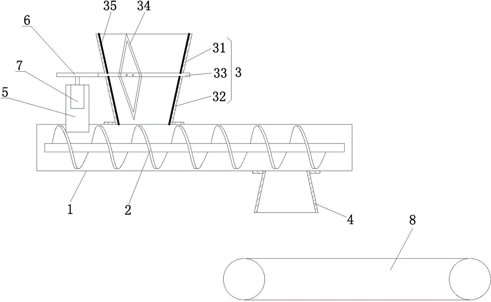
[0010] Such as figure 1 as shown, figure 1 It is a structural schematic diagram of a plastic powder feeding equipment proposed by the present invention.

[0011] refer to figure 1 , a kind of plastic powder feeding equipment proposed by the present invention includes a screw feeding device, and the screw feeding device includes a screw conveying pipe 1, a screw conveying rod 2 arranged in the spiral conveying pipe 1, and an upper end of one side of the spiral conveying pipe 1 The feeding port and the discharging port at the lower end of the other side of the spiral conveying pipe 1 are set, the feeding hopper 3 is arranged at the feeding port, and the discharging hopper 4 is arranged at the discharging port. Hopper 31 and lower feeding hopper 32, the inner diameter of ring gear 33 is consistent with the connecting end inner diameter of upper feeding hopper 31 and lower feeding hopper 32, and shovel knife 34 is fixed on the inner hole wall of ring gear 33, and shovel knife 34...


PUM


Abstract

The invention discloses molding powder feeding equipment which comprises a spiral feeding device, wherein the spiral feeding device comprises a spiral delivery pipe, a spiral delivery rod in the spiral delivery pipe, a feeding opening in the upper end of one side of the spiral delivery pipe, and a discharge opening in the lower end of the other side of the spiral delivery pipe, wherein the feeding opening is provided with a feeding hopper, the discharge opening is provided with a discharge hopper, the feeding hopper comprises an upper feeding hopper and a lower feeding hopper which are connected by a gear ring, the inner hole diameter of the gear ring is identical to the inner diameters of the connecting ends of the upper feeding hopper and the lower feeding hopper, a scraper knife is fixed on the inner hole wall of the gear ring, a U-shaped support is fixed on the spiral delivery pipe, two side surfaces of the U-shaped support are fixed together with the spiral delivery pipe, a driving gear meshed with the gear ring is fixed on the top surface of the U-shaped support, and the driving gear is driven by a decelerating driving mechanism at the inner side of the U-shaped support. The equipment has a simple structure, guarantees that plastic materials fall off from the discharge hopper constantly, lowers the labor intensity of workers, and improves the working efficiency.

Description

technical field [0001] The invention relates to the technical field of conveyors, in particular to plastic powder feeding equipment. Background technique [0002] At present, the plastic powder feeding device includes a screw feeder and a feed hopper and a discharge hopper arranged on the screw feeder. The feed hopper is located at the upper end of one side of the screw feeder, and the discharge hopper is located at the other side of the screw feeder. Both the hopper and the discharge hopper are fixed on the screw feeder, and the plastic powder is continuously added into the feed hopper, and the plastic powder falls into the screw feeder by its own weight, and is pushed to the discharge port through the screw conveying rod. Because the particles of the plastic powder are very fine and sticky, the plastic powder is easy to accumulate and agglomerate in the hopper, and cannot fall into the screw feeder. This requires manual inspection, which not only increases the labor intens...

Claims


Application Information

Patent Timeline
Patent Type & Authority Applications(China)
IPC IPC(8): B65D88/68B65G47/18
Inventor 陶文霖
Owner NINGGUO NINGSHENG RUBBER PROD
Learn More