Reinforcement cage lifting part

A technology of reinforcement cages and hangers, which is applied in the directions of load hanging components, transportation and packaging, can solve the problems affecting the lifting safety of reinforcement cages, the welding quality cannot be guaranteed, the overhead holes are prone to cracks, etc., and achieves simple structure and low cost. , the effect of not easy to get stuck

Active Publication Date: 2014-11-12
ZHEJIANG QIAOXING CONSTR GRP
View PDF4 Cites 4 Cited by
  • Summary
  • Abstract
  • Description
  • Claims
  • Application Information

AI Technical Summary

Problems solved by technology

The existing technology has the following disadvantages. Due to the unevenness of the ground at the orifice, the lifting ring needs to be processed separately according to the site conditions every time, which is time-consuming and labor-intensive. After one use, it needs to be cut off from the steel cage by gas welding, which is basically scrapped. Welding, welding quality cannot be guaranteed
For example, Chinese Patent No. 201220372273.5 discloses a pile foundation reinforcement cage ring, which is inserted into the lower tube through the upper tube and adjusted up and down through the vertically arranged pin holes on the upper tube and the lower tube. There are pin holes, the lower tube is a hollow tube, its strength is not high, and its tensile and load-bearing capacity is not high in some steel cages, and cracks are prone to appear at the overhead holes, which will affect the hoisting safety of the steel cage; at the same time, it adopts The anti-floating clip is not completely fixed on the steel cage, and it is easy to slide out

Method used


Image

  • Reinforcement cage lifting part
  • Reinforcement cage lifting part
  • Reinforcement cage lifting part

Examples


Embodiment 1

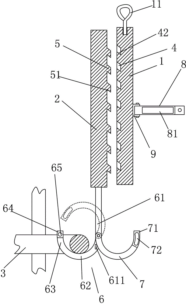
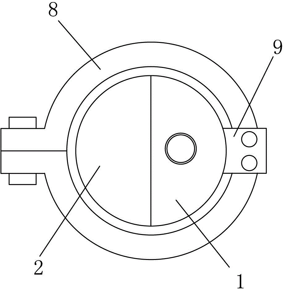
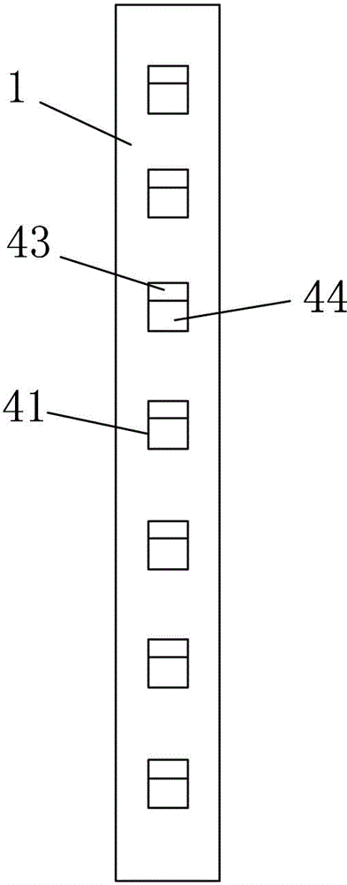
[0034] A reinforcement cage hanger, comprising a lifting rod 1 provided with a ring 11 at the top and a connecting rod 2 provided with a hook 6 for hooking a stirrup 3 on the reinforcement cage, the lifting rod and the connecting rod 2 being fitted with each other The boom is a semi-cylindrical rod, and the rod wall of the lifting rod and the connecting rod includes an arc surface and a plane. The center of the plane of the lifting rod 1 is evenly distributed from top to bottom with a number of inclined buckle grooves 4 arranged obliquely downward from the outside to the inside. The center of the plane of the connecting rod 2 is evenly distributed from top to bottom with an inclined insertion projection 5 that protrudes outwards and is arranged obliquely downward to insert into the inclined buckle groove 4. The inclined buckle groove includes a groove bottom wall 44, a groove upper wall 43, The slot lower wall 42 and the slot side wall 41 for restricting the movement of the inc...

Embodiment 2

[0040] The difference from the above embodiment is that the groove width of the inclined buckle groove is 3 / 4 of the plane width of the lifting rod.

Embodiment 3

[0042] The difference from the above embodiment is that the groove width of the inclined buckle groove is 1 / 2 of the plane width of the lifting rod.

[0043] When in use, match the connecting rod and the lifting rod according to the required length. After the two rods are plugged in, fix the two rods with hoops, screw the ring to the lifting rod, and hook the hook to the stirrup, as shown in the figure Flip the locking hook counterclockwise and fix the locking hook and the hook with the pin.

[0044] The invention has the advantages of simple structure, low cost, convenient assembly and disassembly, reusability and long service life. When the invention is used, the reinforcement cage shakes less, the hoisting is stable, and the operation is safe.


PUM


Abstract

The invention relates to the technical field of buildings, in particular to a reinforcement cage lifting part used for lifting a reinforcement cage in building. The reinforcement cage lifting part comprises a lifting rod and a connection lifting rod which are matched with each other in an inserting mode, the lifting rod and the connection lifting rod are half-cylinder rods, the wall of the lifting rod and the wall of the connection lifting rod comprise arc-shaped surfaces and planes, inclined catching grooves are formed in the center of the plane of the lifting rod, and inclined inserting lugs are arranged at the center of the plane of the connection lifting rod. A hook comprises a direct connection section, a bearing section and a specially-shaped free section, a lock catch hook is hinged to the direct connection section, the upper portion of the specially-shaped free section is provided with a pin hole in the direction perpendicular to the plane where the hook is located, the free end of the lock catch hook is provided with a pin hole corresponding to the pin hole in the hook, the specially-shaped free section is fixedly connected with the free end of the lock catch hook through a plug pin inserted into the pin holes, and the lifting rod is provided with a hoop piece which is used for clasping the lifting rod and the connection lifting rod. The reinforcement cage lifting part is simple in structure, low in cost, convenient to disassemble and assemble, capable of being recycled and long in service life. When the reinforcement cage lifting part is used, the reinforcement cage is little in shake, stable in lifting and safe to operate.

Description

technical field [0001] The invention relates to the technical field of construction, in particular to a tendon cage hanger for lifting a tendon cage in construction. Background technique [0002] The general construction process of pile foundation reinforcement cage installation is as follows: the reinforcement cage is transported to the site, the crane is hoisted into the hole, the appropriate length of the lifting ring is processed according to the positional relationship between the reinforcement cage and the hole, the lifting ring is welded to the reinforcement cage, the position of the reinforcement cage is adjusted, and the The steel cage is fixed. The existing technology has the following disadvantages. Due to the unevenness of the ground at the orifice, the lifting ring needs to be processed separately according to the site conditions every time, which is time-consuming and labor-intensive. After one use, it needs to be cut off from the steel cage by gas welding,...

Claims


Application Information

Patent Timeline
Patent Type & Authority Applications(China)
IPC IPC(8): B66C1/10
Inventor 吴烨钱旭亮罗瑛李翔陈敏张思懿
Owner ZHEJIANG QIAOXING CONSTR GRP
Why Eureka
Try Eureka