
Compensation type steady flow water supply device and its control method

The technology of a water supply device and a control method, which is applied to the configuration of water supply devices, water supply pools, water conservation, etc., can solve problems such as water storage pollution, and achieve the effects of preventing air pollution and suppressing the generation of vacuum

Active Publication Date: 2015-09-30
广一泵业有限公司
View PDF7 Cites 0 Cited by
  • Summary
  • Abstract
  • Description
  • Claims
  • Application Information

AI Technical Summary

Problems solved by technology

[0003] One of the objectives of the present invention is to propose a compensation type steady flow water supply device, which can solve the problem of water storage pollution

Method used


Image

  • Compensation type steady flow water supply device and its control method

Examples


Embodiment Construction

[0024] In the following, the invention will be further described in conjunction with the accompanying drawings and specific embodiments.

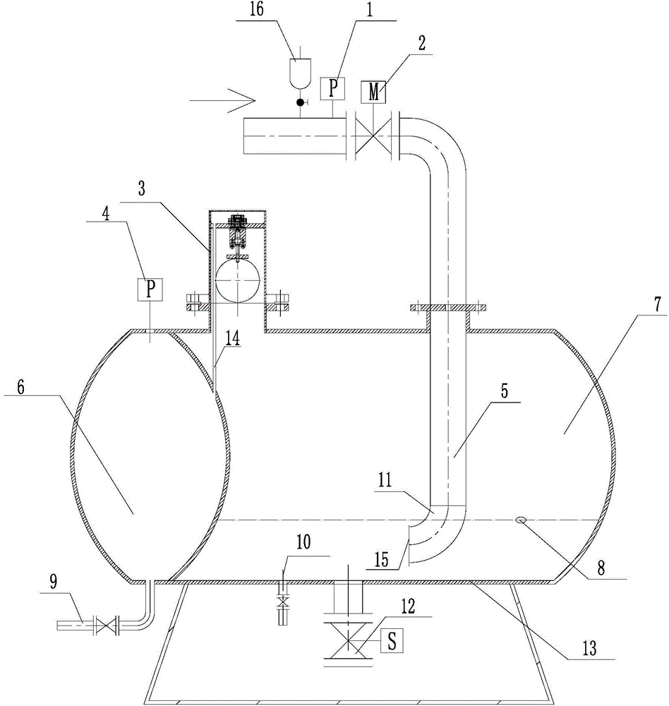
[0025] Such as figure 1 As shown, a compensation type steady flow water supply device includes a regulating tank 13, a water inlet pipe 5, a vacuum suppressor 3, a first pressure sensor 1, a second pressure sensor 4, an inlet solenoid valve 2, an outlet solenoid valve 12, Liquid level sensor 8, elbow 11, baffle plate 15, automatic exhaust valve 16 and controller.

[0026] A first cavity 7 and a second cavity 6 are arranged at intervals in the regulating tank 13, and the second cavity 6 communicates with the first cavity 7 through the air duct 14 and the vacuum suppressor 3 in turn, and the vacuum suppressor 3 Located at the top of the first cavity 7 .

[0027] The outlet of the water inlet pipe 5 is located in the first cavity 7, the inlet of the water inlet pipe 5 is located outside the regulating tank 13 and is used to connect with the ...


PUM


Abstract

The invention relates to a compensation type flow stabilizing and water supplying device and a control method thereof. The device comprises an adjusting tank, a water inlet pipe, a vacuum suppressor, a first pressure sensor, a second pressure sensor, a water inlet electromagnetic valve, a water outlet electromagnetic valve and a controller, wherein the adjusting tank is provided with a first cavity and a second cavity. The second cavity is communicated with the first cavity sequentially through an air guide pipe and the vacuum suppressor. An outlet of the water inlet pipe is located in the first cavity. An inlet of the water inlet pipe is located outside the adjusting tank and used for being connected with a water supply pipeline. The water inlet electromagnetic valve is installed in the water inlet pipe and used for controlling opening or closing of the water inlet pipe. The first pressure sensor is installed in the water inlet pipe and located between the water inlet end of the water inlet electromagnetic valve and the inlet of the water inlet pipe. A water outlet is formed in the bottom of the first cavity. The water outlet electromagnetic valve is installed in the water outlet and used for controlling opening or closing of the water outlet. The second pressure sensor is installed in the second cavity. The adjusting tank is filled with inert gas. The device effectively prevents air pollution.

Description

technical field [0001] The invention relates to a non-negative pressure water supply technology. Background technique [0002] With the continuous increase of high-rise buildings and the continuous improvement of urban water pipe network facilities, non-negative pressure equipment that is directly connected in series to the water pipe network for superimposed water supply has emerged as the times require. Compared with traditional secondary water supply equipment, non-negative pressure water supply equipment has the advantages of energy saving, sanitation, small footprint, and convenient management. When the water consumption peaks and the tap water inlet pressure is insufficient, the difference compensation can also be realized. The existing method is that when the user's water consumption is greater than the tap water intake and the pressure in the flow compensation tank is lower than one atmospheric pressure, the vacuum suppressor installed on the flow compensation tank ...

Claims


Application Information

Patent Timeline
Patent Type & Authority Patents(China)
IPC IPC(8): E03B11/06E03B7/07
CPCY02A20/00
Inventor 李伟方朱文学
Owner 广一泵业有限公司
Learn More