
Frequency calibration method, device and system for oven controlled crystal oscillator

A constant temperature crystal oscillator and crystal oscillator technology, applied in the direction of power oscillators, electrical components, etc., can solve the problems that cannot meet the high performance indicators of constant temperature crystal oscillators, are not accurate enough, and cannot continuously guarantee stable output.

Active Publication Date: 2014-11-12
GUANGDONG DAPU TELECOM TECH CO LTD
View PDF5 Cites 12 Cited by
  • Summary
  • Abstract
  • Description
  • Claims
  • Application Information

AI Technical Summary

Problems solved by technology

This method of changing the frequency parameters of the crystal oscillator through manual debugging is not scientific and accurate enough, and it is easy to cause inaccurate frequency accuracy or artificial selection errors, resulting in the constant temperature crystal oscillator not meeting its required output accuracy, and even unable to continuously ensure stability. output; in addition, low production efficiency is also a great disadvantage of manual debugging, which is far from meeting the high performance indicators of constant temperature crystal oscillators

Method used


Image

  • Frequency calibration method, device and system for oven controlled crystal oscillator
  • Frequency calibration method, device and system for oven controlled crystal oscillator
  • Frequency calibration method, device and system for oven controlled crystal oscillator

Examples


Embodiment 1

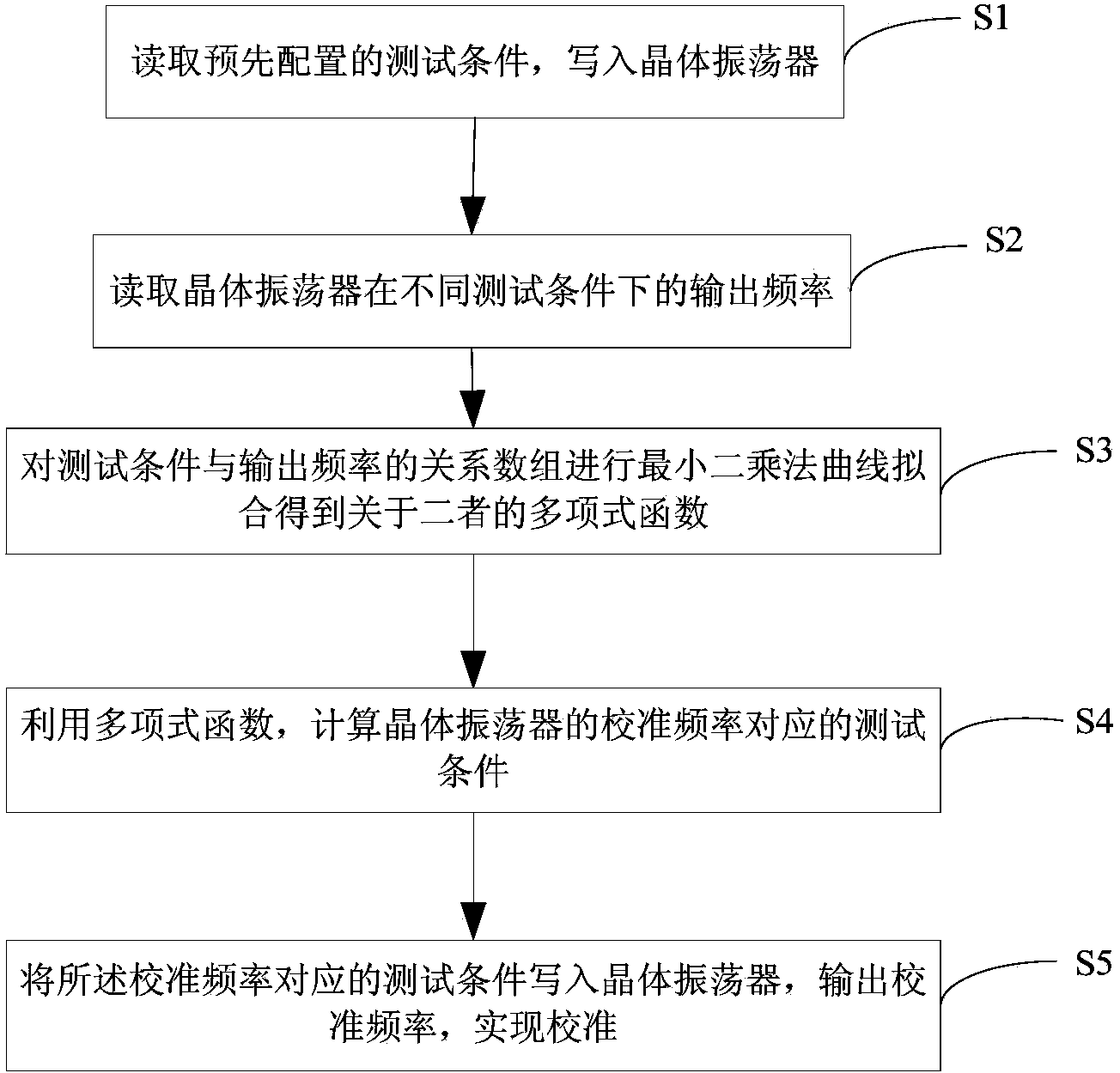
[0049] figure 1 It is a flow chart of a frequency calibration method for an ovenized crystal oscillator provided in Embodiment 1 of the present invention. Such as figure 1 As shown, a kind of constant temperature crystal oscillator frequency calibration method described in the present invention comprises:

[0050] S1. Read the pre-configured test conditions and write them into the crystal oscillator;

[0051] S2, read the output frequency of the crystal oscillator under different test conditions;

[0052] S3, performing least squares curve fitting on the relationship array of test conditions and output frequency to obtain a polynomial function about test conditions and output frequency;

[0053] S4. Using a polynomial function, calculate the test condition corresponding to the calibration frequency of the crystal oscillator;

[0054] S5. Write the test condition corresponding to the calibration frequency into the crystal oscillator, output the calibration frequency, and real...

Embodiment 2

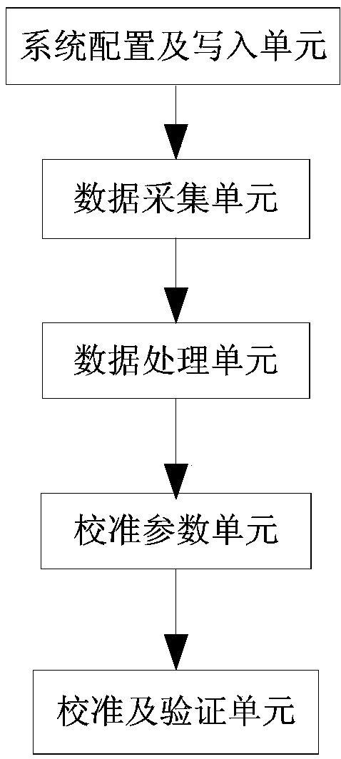
[0068] Embodiment 2: The following is the device embodiment of the embodiment of the present invention. The method embodiment, device embodiment, and system embodiment of the present invention belong to the same concept. Details that are not described in detail in the device embodiment and system embodiment can be Refer to the above method embodiment. figure 2 It is a schematic structural diagram of a constant temperature crystal oscillator frequency calibration device provided in Embodiment 2 of the present invention. Such as figure 2 As shown, a constant temperature crystal oscillator frequency calibration device according to the present invention includes:

[0069] The system configuration and writing unit is used to read the pre-configured test conditions and write to the crystal oscillator;

[0070] The data acquisition unit is used to read the output frequency of the crystal oscillator under different test conditions;

[0071] The data processing unit is used to per...

Embodiment 3

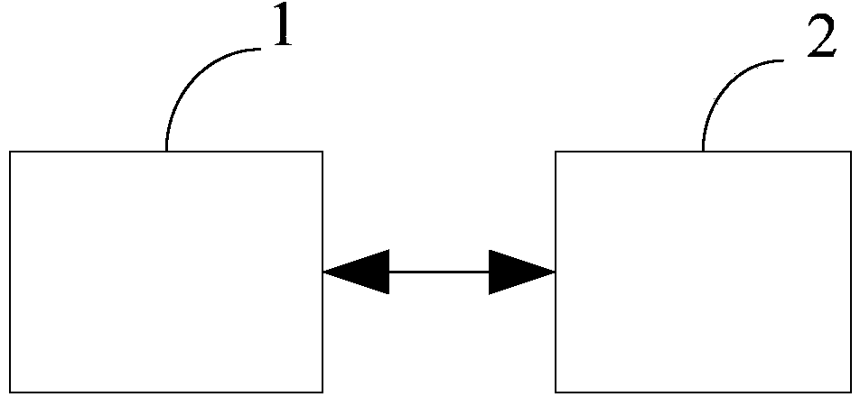
[0084] Embodiment 3: The following is the system embodiment of the embodiment of the present invention. The method embodiment, device embodiment, and system embodiment of the present invention belong to the same concept. Details that are not described in detail in the device embodiment and system embodiment can be Refer to the above method embodiment. image 3 It is a structural schematic diagram of a constant temperature crystal oscillator frequency calibration system provided by Embodiment 3 of the present invention. Such as image 3 As shown, a constant temperature crystal oscillator frequency calibration system according to the present invention includes: a test hardware device 2, and a PC 1 connected to the test hardware device 2 through a communication interface;

[0085]The PC 1 is used to read preset test conditions, control the test hardware device 2 to write the test conditions into the crystal oscillator, read the output frequency of the crystal oscillator returned...


PUM


Abstract

The invention relates to a frequency calibration method, device and system for an oven controlled crystal oscillator. The method comprises the steps that preset test conditions are read and written in the crystal oscillator; output frequencies of the crystal oscillator under the different test conditions are read; least squares curve fitting is performed on relation arrays of the test conditions and the output frequencies to obtain polynomial functions about the test conditions and the output frequencies; the test condition corresponding to the calibration frequency of the crystal oscillator is calculated through the polynomial functions and is written in the crystal oscillator; the output calibration frequency of the crystal oscillator under the test condition corresponding to the calibration frequency is read and verified; if the output calibration frequency meets the range of frequency accuracy, calibration is over; or else, the calibration continues to be performed after coefficients of the polynomial functions are adjusted. According to the frequency calibration method, device and system, the frequency calibration of the oven controlled crystal oscillator can be automatically completed, measuring errors are reduced, and the purposes of performing frequency calibration automatically and accurately and enhancing production efficiency are achieved.

Description

technical field [0001] The invention relates to the technical field of crystal oscillators, in particular to a frequency calibration method, device and system for a constant temperature crystal oscillator. Background technique [0002] At present, the frequency accuracy calibration of the constant temperature crystal oscillator is carried out by manually controlling the test equipment, changing the frequency output of the crystal oscillator by manually changing the temperature value, and then manually determining whether it is within the frequency accuracy range of the crystal. This method of changing the frequency parameters of the crystal oscillator through manual debugging is not scientific and accurate enough, and it is easy to cause inaccurate frequency accuracy or artificial selection errors, resulting in the constant temperature crystal oscillator not meeting its required output accuracy, and even unable to continuously ensure stability. output; in addition, low produ...

Claims


Application Information

Patent Timeline
Patent Type & Authority Applications(China)
IPC IPC(8): H03B5/04
Inventor 李坤然
Owner GUANGDONG DAPU TELECOM TECH CO LTD
Learn More