Channel state information transmission method, user equipment and base station in MIMO system
A technology of channel state information and transmission method, which is applied in the field of user equipment (User Equipment), can solve the problems of not being able to describe the long-term statistical characteristics of the channel well, the impact of system precoding performance, and inapplicability, so as to improve the precoding performance and effectively Effect of CSI feedback and precoding manipulation
- Summary
- Abstract
- Description
- Claims
- Application Information
AI Technical Summary
Problems solved by technology
Method used
Image
Examples
Embodiment 1
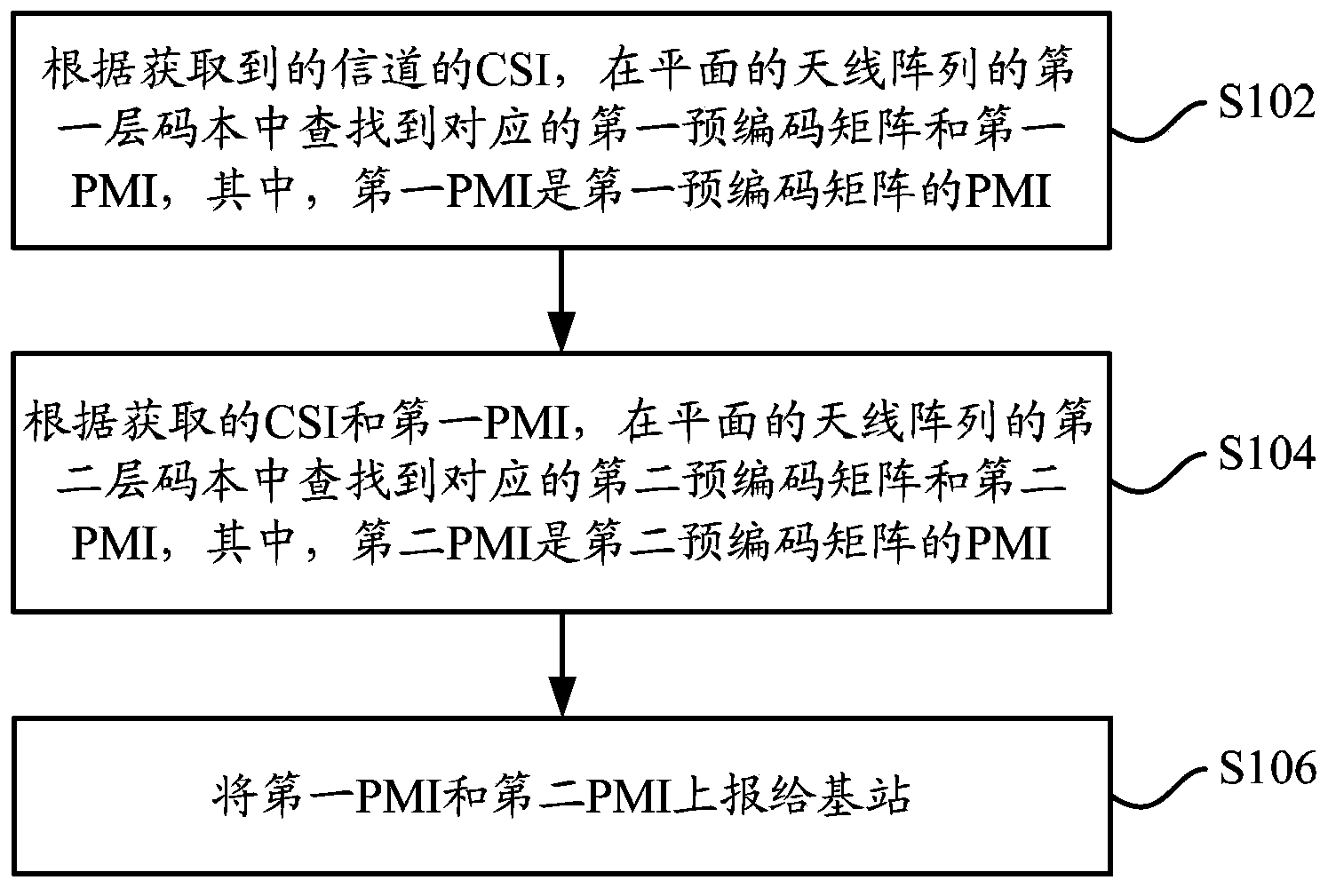
[0038] The CSI transmission method in the MIMO system of Embodiment 1 may be performed by any UE. Such as figure 1 As shown, the method includes the following steps:
[0039] Step S102, according to the obtained CSI of the channel, find the corresponding first precoding matrix and first PMI in the first layer codebook of the planar antenna array, wherein the first PMI is the PMI of the first precoding matrix ;
[0040] In actual implementation, the UE can perform channel estimation according to the received pilot sequence to obtain CSI.
[0041] Since each precoding matrix in the codebook corresponds to a PMI (Precoding Matrix Indicator, precoding matrix indication), the corresponding precoding matrix can be found in the first layer codebook of the planar antenna array according to the obtained CSI. A coding matrix (called a first precoding matrix) and a PMI corresponding to the first precoding matrix (called a first PMI). The first-level codebook of the planar antenna arr...
Embodiment 2
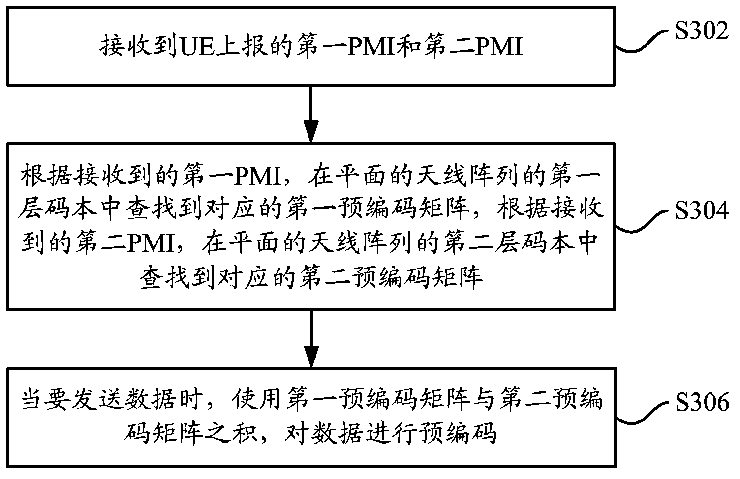
[0065] The CSI transmission method in the MIMO system of Embodiment 2 may be performed by any base station. Such as figure 2 As shown, the method includes the following steps:
[0066] Step S302, receiving the first PMI and the second PMI reported by the UE;
[0067] In actual implementation, the base station acquires the first PMI and the second PMI from the uplink channel.
[0068] Step S304, according to the received first PMI, find the corresponding first precoding matrix in the first layer codebook of the planar antenna array, and according to the received second PMI, find the corresponding first precoding matrix in the second layer of the planar antenna array Finding the corresponding second precoding matrix in the codebook;
[0069] Among them, the first-level codebook of the planar antenna array is obtained by direct product operation on the first-level codebook of the linear array of the planar antenna array in the x-axis direction and the y-axis direction, and th...
Embodiment 3
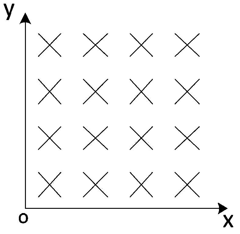
[0074] The third embodiment is based on the codebook design idea of discrete Fourier (DFT), as image 3 The URA 4×4 layout of 32 dual-polarized antenna elements shown is taken as an example to describe the methods in the first and second embodiments above in detail. exist image 3 In , each line segment represents one antenna element, and the line segments with the same direction indicate that the polarization directions of the corresponding antenna elements are the same.
[0075] The specific construction method of the first-layer codebook and the second-layer codebook for URA includes the following steps:
[0076] Step S401, will be as image 3 The straight lines where the two mutually perpendicular sides of the shown URA are located are taken as the x-axis direction and the y-axis direction;
[0077] Step S402, for the linear array corresponding to the URA in the x-axis direction, construct its first-layer codebook based on the rotation DFT matrix, which is recorded as...
PUM
 Abstract
Description
Claims
Application Information
 - R&D
- Intellectual Property
- Life Sciences
- Materials
- Tech Scout
- Unparalleled Data Quality
- Higher Quality Content
- 60% Fewer Hallucinations
Browse by: Latest US Patents, China's latest patents, Technical Efficacy Thesaurus, Application Domain, Technology Topic, Popular Technical Reports.
© 2025 PatSnap. All rights reserved.Legal|Privacy policy|Modern Slavery Act Transparency Statement|Sitemap|About US| Contact US: help@patsnap.com


