Novel large-channel electrophoresis microchip

A large channel and microchip technology, which is applied in the direction of material analysis, measurement device, and instrument by electromagnetic means, can solve the problem of low sample load of capillary microfluidic chip, and achieve the effect of solving the excessive Joule heating effect.

Active Publication Date: 2014-11-19
TIANJIN UNIV
View PDF3 Cites 7 Cited by
  • Summary
  • Abstract
  • Description
  • Claims
  • Application Information

AI Technical Summary

Problems solved by technology

[0005] In order to solve the problems existing in the prior art, the present invention provides a novel large-channel electrophoresis microchip, which overcomes the problem of low sample loading of the capillary microfluidic chip in the prior art

Method used


Image

  • Novel large-channel electrophoresis microchip
  • Novel large-channel electrophoresis microchip
  • Novel large-channel electrophoresis microchip

Examples


Embodiment 1

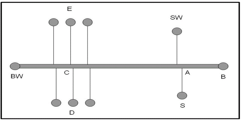
[0040] designed as figure 1 The chip shown, where the distance between B and BW is 10.5cm, and the channel diameter is 1mm; A is the injection site; the distance between S and SW is 1.1cm; the stagger distance between A, S and A, SW is 1mm; A and C The distance between them is 6.5cm; the chips are made according to the steps in the technical scheme. Use the "double T-type" channel electrosampling method to analyze organic acid samples:

[0041] Experimental conditions: buffer: 10mM acetic acid-sodium acetate buffer (containing 0.6% HEC) at pH4.0; sample: 1mg / mL benzoic acid, 2mg / mL p-toluenesulfonic acid mixture; effective length / total length=6.5cm / 10.5cm; detection wavelength: 259nm; injection voltage 300V; injection current 300μA; injection time 60s; negative electrode injection; separation voltage 1000V; current 220-240μA; / min. The result is as Figure 6 , where 1 is p-toluenesulfonic acid; 2 is benzoic acid.

Embodiment 2

[0043] designed as figure 1 The chip shown, where the distance between B and BW is 10.5cm, and the channel diameter is 1mm; A is the injection site; the distance between S and SW is 1.1cm; the stagger distance between A, S and A, SW is 1mm; A and C The distance between C and D is 6.5cm; the channel between C and D adopts the method of inserting a capillary, and the effective length of the channel / total length=13.5cm / 27.5cm is obtained; the chip is manufactured according to the steps in the technical solution (c). Using the "double T-type" channel electrosampling method and the three-electrode transfer mode to analyze organic acid samples:

[0044] Experimental conditions: one-dimensional buffer: 10mM acetic acid-sodium acetate buffer at pH4.0; two-dimensional buffer: 40mM acetic acid-sodium acetate buffer at pH4.5; samples: 1mg / mL benzoic acid, 2mg / mL Mixed solution of toluenesulfonic acid; negative electrode sample injection; 300V, 90s; transfer voltage: point B is -1000V, p...


PUM

PropertyMeasurementUnit
Diameteraaaaaaaaaa
Total lengthaaaaaaaaaa
Lengthaaaaaaaaaa

Abstract

The invention discloses a novel large-channel electrophoresis microchip. PDMS is used as a material, a separating channel which is 0.8-1.2mm in diameter and 8-30cm in total length is formed in the chip, buffer slots are fixed in two ends of the separating channel, an inner refrigerating capillary is fixed in the separating channel, two ends of the inner refrigerating capillary are fixed by hollow fiber membranes, a sample introduction channel perpendicular to the separating channel is arranged at a position being 0.5-2cm away from one end of the separating channel, a transferring channel is arranged at a position being 6-20cm away from the sample introduction channel and is perpendicular to the separating channel, and the material adopts the PDMS or a quartz capillary; the chip is 8-30cm in total length, 2-9cm in width and 0.2-0.7cm in thickness; the novel large-channel electrophoresis microchip with millimeter-sized separating channel is developed through a micro-fluidic chip measure on the basis of the WBE technology, so that the sample loading quantity is improved to be equivalent to that of the WBE, severe Joule heating effect is solved, the zero dead volume connection of the large channel and the transferring channel is realized, and the whole process of one-dimensional analysis and two-dimensional transferring of the samples can be carried out through voltage control.

Description

technical field [0001] The invention belongs to the technical field of microfluidic chip electrophoresis analysis, and in particular relates to an electrophoresis microchip. Background technique [0002] Lab-on-a-chip or Miniaturized Total Analysis System (μ-TAS) was first proposed by Manz and Widmer in 1990, and has been developed in the following 20 years. Continuous innovation and development. Generally, the core of microchip electrophoresis technology is high-speed capillary electrophoresis separation in channels with a width of 50-100 μm and a depth of 10-20 μm, which has the advantages of fast analysis speed, high efficiency, low cost, easy automation and high-throughput quantification. Research hotspots in the field of analytical chemistry. With the deepening of current biotechnology research, conventional one-dimensional analysis is difficult to meet the peak capacity requirements of complex samples. Therefore, chip electrophoresis has been developing in the direct...

Claims


Application Information

Patent Timeline
IPC IPC(8): B01L3/00G01N27/447
Inventor 李优鑫包建民赵璐萌
Owner TIANJIN UNIV
Why Eureka
Try Eureka