Beam forming device and method

A beam and ring beam technology, applied in laser welding equipment, welding equipment, metal processing equipment, etc., can solve the problems of low spiral drilling processing efficiency, low energy utilization rate, melting and other problems

Active Publication Date: 2014-11-19
北京中科镭特电子有限公司
View PDF11 Cites 14 Cited by
  • Summary
  • Abstract
  • Description
  • Claims
  • Application Information

AI Technical Summary

Problems solved by technology

[0005] The disadvantage of spiral drilling is that the processing efficiency is relatively l...

Method used


Image

  • Beam forming device and method
  • Beam forming device and method
  • Beam forming device and method

Examples


Embodiment Construction

[0034] The present invention is described in detail below in conjunction with accompanying drawing:

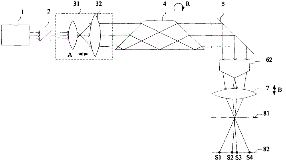
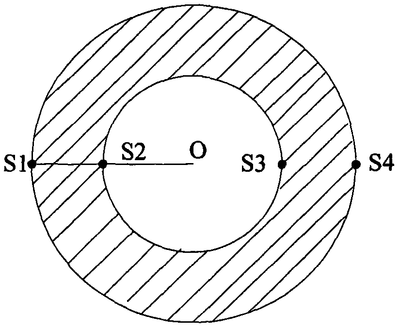
[0035] Such as figure 1 As shown, the light beam emitted by the laser 1 passes through the optical gate 2 to control whether to continue to transmit. The distance between the lens 31 and the lens 32 is relatively adjustable, and is used to adjust the divergence angle and spot size of the laser beam. The Dove prism 4 is installed in the hollow shaft rotating motor, so that the Dove prism rotates R around the optical axis, and the light beam emitted from the Dove prism 4 will also rotate accordingly. The rotating laser beam enters the plane reflector 5, and the propagation direction of the laser is changed to vertical propagation. The vertically propagating laser beam enters the positive axicon 62 and the focusing lens 7, and the outgoing beam is a rotating ring beam, such as figure 2 As shown, the spot radius OS2 of the ring beam and the ring width S1S2 will change with the...


PUM


Abstract

The invention provides a beam forming device and method. The beam forming device is formed by arranging a laser device, a pair of lenses, a Dove prism, a plane mirror, a regular axicon and a focusing lens in sequence in the direction of an optical axis. The distance between the lenses is adjustable so that the spot size and divergence angle of outgoing beams of the laser device can be adjusted. The Dove prism is installed in a hollow shaft rotary motor and rotates with the optical axis serving as the center, and the outgoing beams from the Dove prism also rotate with the Dove prism. The plane mirror is used for deflecting the transmission direction of the beams. The position of the focusing lens in the transmission direction of the beams is adjustable, and the outgoing beams are a bunch of rotary hollow annular beams after passing through the focusing lens.

Description

technical field [0001] The invention belongs to the technical field of laser processing, and relates to a beam forming device and a method thereof in laser drilling equipment, and is especially suitable for micro-hole processing of high-hard-brittle materials. Background technique [0002] Laser processing technology has penetrated into all walks of life, especially in high-precision industries such as microelectronics and aerospace. The requirements for processing size are getting smaller and higher, and laser processing has become an irreplaceable Methods. In the type of material processing, drilling occupies a large proportion. There are generally four types of laser drilling: single-pulse drilling, multi-pulse drilling, rotary drilling, and spiral drilling. [0003] At present, the better technology is spiral drilling. After the laser is focused by the focusing lens, it acts on the surface of the workpiece. The beam moves along the processing track. After a layer of ma...

Claims


Application Information

Patent Timeline
IPC IPC(8): B23K26/064B23K26/073
CPCB23K26/0643B23K26/0648B23K26/0652B23K26/073
Inventor 李俊李纪东杨顺凯
Owner 北京中科镭特电子有限公司
Why Eureka
Try Eureka