Engine supporting foot for flexible base

A flexible base and engine technology, applied in the direction of power plants, jet propulsion devices, internal combustion propulsion devices, etc., can solve problems such as damage and engine deformation

Inactive Publication Date: 2014-11-19
HENAN DIESEL ENGINE IND
View PDF7 Cites 0 Cited by
  • Summary
  • Abstract
  • Description
  • Claims
  • Application Information

AI Technical Summary

Problems solved by technology

[0003] The purpose of the present invention is to propose an engine foot for a flexible base to solve the problems of deformation of the engine and destruction of weak points due to torsional deformation of the flexible base when the engine is installed on the flexible base

Method used


Image

  • Engine supporting foot for flexible base
  • Engine supporting foot for flexible base
  • Engine supporting foot for flexible base

Examples


Embodiment Construction

[0011] The present invention is described in conjunction with accompanying drawing and specific embodiment:

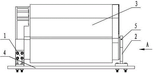
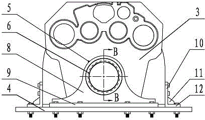
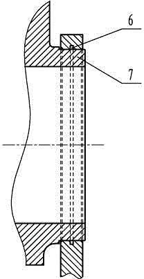
[0012] An engine foot for a flexible base, including: a rear foot and a front foot; there are two rear feet 1, which are arranged at the rear end (flywheel end) of the engine, and consist of a side plate 10, a bottom plate 12, ribs The plate 11 is welded; 4 bolt mounting holes are arranged on the side plate 10, and the rear end leg of the side plate 10 is connected with the engine 3 through 4 bolts; Bolts connect the rear end leg 1 with the flexible base 4 . The front-end support foot 2 is arranged at the front end of the engine (shock absorber end), and is welded by a vertical plate 8 and a horizontal plate 9; a shaft hole is arranged on the vertical plate 8, and the shaft hole is matched with the support shaft provided on the engine with clearance , the engine support shaft can rotate freely in the shaft hole, and there is an oil groove 6 for lubrication in the enti...


PUM


Abstract

The invention belongs to the technology of engine mounting in engineering machines, and relates to an engine supporting foot for a flexible base. The engine supporting foot comprises rear-end supporting foot bodies (1) at the rear end of an engine and a front-end supporting foot body (2) at the front end of the engine. Side plates (10) and bottom plates (12) of the rear-end supporting foot bodies (1) enable the rear-end supporting foot bodies (1) to be connected with the engine (3) and the flexible base (4) respectively. A cross plate of the front-end supporting foot body (2) enables the front-end supporting foot body (2) to be connected with the flexible base (4). A shaft hole in clearance fit with a bearing shaft (7) on the engine is formed in a vertical plate (8) of the front-end supporting foot body (2), and lubrication is provided for rotation of the bearing shaft (7) of the engine in the shaft hole through an oil cup (5), an oil injection hole and an oil tank (6). The engine supporting foot effectively solves the problem that when the engine is arranged on the flexible base, due to the fact that torsional deformation happens to the flexible base, the engine is deformed, and the weak portion is damaged.

Description

technical field [0001] The invention belongs to the technical field of engine installation in construction machinery, and relates to an engine support foot used for a flexible base. Background technique [0002] When the engine is applied to construction machinery, it is necessary to design a special base for installing the engine, install the engine on the base, and connect the engine and the base through a foot. When the engine is installed in a fixed position, common supporting feet are used to connect the engine and the base through bolts, and the engine and the supporting feet, and the supporting feet and the base are completely fastened after the bolts are tightened. When the engine is installed on moving construction machinery such as automobile compartments and complete sets of walking machinery, the construction machinery will be deformed to a certain extent due to the uneven road surface, engine vibration, and poor rigidity of the construction machinery itself when...

Claims


Application Information

Patent Timeline
IPC IPC(8): B60K5/12
Inventor 付艳萍张鹏飞包方芳汤守哲孟亮虎
Owner HENAN DIESEL ENGINE IND
Why Eureka
Try Eureka