
Gear signal processing output signal digital differential control booster system

A technology of output signal and signal processing, which is applied in the field of front wheel and rear wheel differential distribution assist bicycle power supply controller system, which can solve the problem of no electronic differential module and other problems

Active Publication Date: 2016-06-22
江苏鸿迅机车有限公司
View PDF8 Cites 0 Cited by
  • Summary
  • Abstract
  • Description
  • Claims
  • Application Information

AI Technical Summary

Problems solved by technology

[0005] The Chinese patent 201210399458.X applied by Chengdu Lianteng Power Control Technology Co., Ltd. discloses a dual-motor controller with electronic differential function, but there is no specific design of electronic differential module

Method used


Image

  • Gear signal processing output signal digital differential control booster system
  • Gear signal processing output signal digital differential control booster system
  • Gear signal processing output signal digital differential control booster system

Examples


Embodiment 1

[0057] Embodiment 1. Digital differential control booster system for gear signal processing output signal

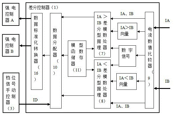
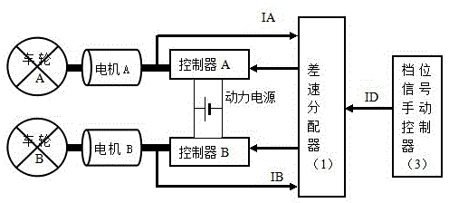
[0058] like figure 1 , 2 , including the two wheels of the electric assist bicycle: wheel A and wheel B, and the motor A driving the wheel A and the motor B driving the wheel B, including the gear signal manual controller 3 of the electric assist bicycle, and also including the differential controller 1 ,

[0059] The differential controller 1 and the motor A are connected by the controller A, and the controller A uses the control signal given by the differential controller 1 to control the power supply to supply power to the wheel A;

[0060] The differential controller 1 and the motor B are connected by the controller B, and the controller B uses the control signal given by the differential controller 1 to control the power supply to supply power to the wheels B.

[0061] Take the feedback control signal current IA between the motor A and the controller A and input ...

Embodiment 2

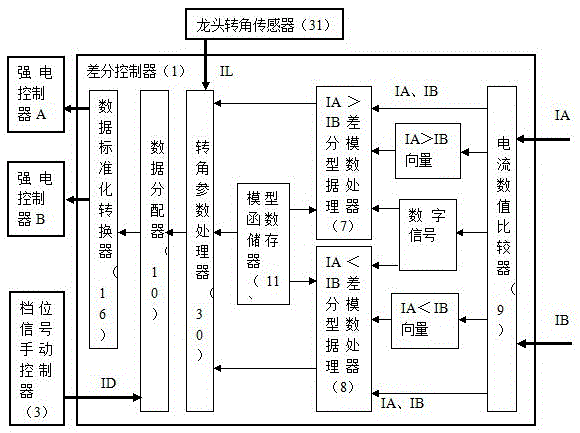
[0086] Embodiment 2. Digital differential control booster system with gear signal processing output signal of rotation angle parameter processor

[0087] like image 3 , 4 , as the whole structure of embodiment 1, and IA>IB differential model data processor 7 and IA<IB differential model data processor 8 are connected with data distributor 10 through corner parameter processor 30, and corner parameter processor 30 is also connected with faucet The angle sensor 31 is connected.

[0088] A pressure sensor is arranged on the human seat cushion of the power-assisted bicycle, or on the elastic part connected with the cushion, and the pressure sensor is connected with the data distributor 10 in the differential controller 1, and the pressure signal of the pressure sensor is respectively sent to two data distributors in the data distributor 10. The control digital signals are processed in the same proportion to increase or the same proportion to decrease.


PUM


Abstract

The digital differential control booster system of the present invention, which processes the output signal of the gear signal, belongs to the power supply controller system of the front wheel and the rear wheel with differential distribution of the differential power supply for the booster bicycle. It includes two wheels and two motors of the electric power-assisted bicycle, a manual controller for the gear position signal, and a differential controller. The differential controller includes three modules connected in sequence; the first module feedbacks and controls the original input signal used for control The signal current IA and IB are numerically compared and processed; the second module uses the set model function to perform model function processing on the data of the first module; the third module inputs the gear signal ID of the gear signal manual controller to the differential controller The data distributor, so that the control data obtained by the controllers A and B not only have the feedback control signal, but also have the elements of the gear signal ID. Advantages: Differentially control and supply power to the two motors of the front and rear wheels of the power-assisted bicycle. The content of the differential control is the pre-set model function processing.

Description

technical field [0001] The invention belongs to a booster controller system of an electric power-assisted bicycle, in particular to a power supply controller system for a bicycle with differential power distribution between the front wheel and the rear wheel for differential power supply. Background technique [0002] The Chinese patent 201210011641.8 applied by Hunan Shengtong Technology Group Co., Ltd. proposes a dual hub motor drive system adaptive balance steering control method, but does not provide the technical design of a special processor for electronic differential. [0003] The Chinese patent 201110358020.2 applied by Hunan Shengtong Technology Group Co., Ltd. is a centralized controller for electronic differential speed and speed regulation of dual hub motors, but there is no specific design of the electronic differential speed module. [0004] Co., Ltd. Hitachi Manufacturing Co., Ltd. 01122460.6 This paper discloses a transmission, which includes a mechanism for...

Claims


Application Information

Patent Timeline
Patent Type & Authority Patents(China)
IPC IPC(8): B60L15/32B62M6/45
Inventor 黄强
Owner 江苏鸿迅机车有限公司
Learn More