
Capture mechanism and multi-level lead screw non-cooperative target docking mechanism

A technology of docking mechanism and lead screw, which is applied in the field of aerospace to achieve the effect of avoiding tilt, simplifying mechanism and avoiding gap escape

Active Publication Date: 2014-11-19
HARBIN INST OF TECH
View PDF8 Cites 17 Cited by
  • Summary
  • Abstract
  • Description
  • Claims
  • Application Information

AI Technical Summary

Problems solved by technology

[0004] The purpose of the present invention is to provide a multi-stage lead screw non-cooperative target docking mechanism to solve the problems of identifying, measuring and capturing the target under the non-cooperative situation of the spacecraft

Method used


Image

  • Capture mechanism and multi-level lead screw non-cooperative target docking mechanism
  • Capture mechanism and multi-level lead screw non-cooperative target docking mechanism
  • Capture mechanism and multi-level lead screw non-cooperative target docking mechanism

Examples


specific Embodiment approach 1

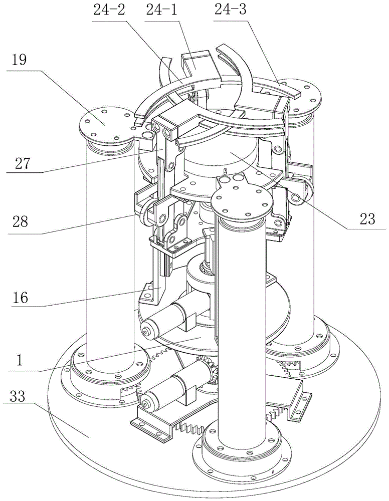
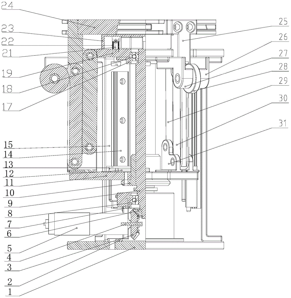
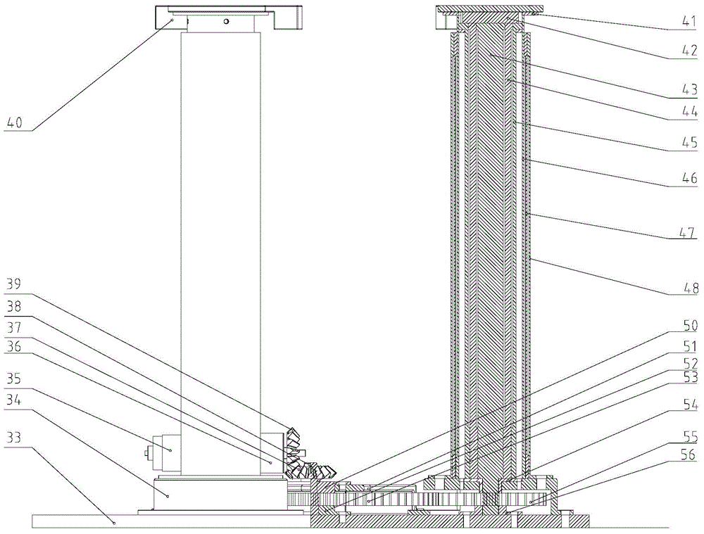
[0010] Specific implementation mode one: combine figure 1 with figure 2 Describe this embodiment, which includes a base 1, a bevel gear pair, a motor 5, a main screw 9, a nut 10, a support frame 11, a gripper end mechanism 24, three sliders 13, and three slide rails 14 , three slide rail brackets 16, upper cover 19, three rollers 28 and three linkages and three sets of linkages, the output shaft 4 of the first motor 5 is connected to the input end of the bevel gear pair, and the bevel gear pair The output end of the main screw 9 is connected with one end of the main screw 9. The other end of the main screw 9 passes through the support frame 11 and then the nut 10 is installed. The nut 10 is fixed on the upper surface of the support frame 11. The three slide rail brackets 16 The cloth is arranged and fixed between the base 1 and the upper cover 19 and is evenly distributed along the circumferential direction of the base 1. The slide rail 14 is fixed on the side wall of each s...

specific Embodiment approach 2

[0011] Specific implementation mode two: combination figure 1 To illustrate this embodiment, the terminal mechanism 24 of this embodiment includes three grippers, which are respectively defined as a first gripper, a second gripper and a third gripper, and each gripper is connected by a connecting handle 24- 1. The first curved rod 24-2 and the two second curved rods 24-3 are integrated, one side of the connecting handle 24-1 is fixedly connected to one end of the first curved rod 24-2, and the connecting handle 24-1 The other side is fixedly connected with two second arc rods 24-3, and the two second arc rods 24-3 are arranged side by side from top to bottom, and each hinge frame 25 is fixedly connected with the corresponding connecting handle 24-1, and the second The first arc rod of the first grabbing part is intersected with the two second arc rods of the second grabbing part, and the first arc bar of the second grabbing part is intersected with the two second arc bars of t...

specific Embodiment approach 3

[0012] Specific implementation mode three: combination figure 1 with figure 2 Describe this embodiment, present embodiment also comprises buffer platform 23, a plurality of buffer spring columns 21 and a plurality of buffer springs 22, buffer platform 23 is located on the upper end surface of loam cake 19, and a plurality of buffer spring columns 21 are contained in buffer platform 23 inside, and each buffer spring column 21 is equipped with a buffer spring 22. Other implementation manners are the same as the specific implementation manner 1.


PUM


Abstract

The invention discloses a capture mechanism and a multi-level lead screw non-cooperative target docking mechanism, and relates to the technical field of aerospace. The mechanisms solve the problems about operation such as recognition, measurement and capture on a target under the non-cooperative situation of an existing spacecraft. According to the scheme of the capture mechanism, a first motor drives a linkage mechanism to rise to a grab portion to be in an open state, and the grab portion is driven by the linkage mechanism to rapidly fold and contract backwards. According to the scheme of the docking mechanism, the docking mechanism is composed of the capture mechanism and a telescoping mechanism, wherein the telescoping mechanism achieves stretching and contraction in the mode that a second motor drives three levels of lead screws to stretch out level by level through a bevel gear drive mechanism and a spur gear drive mechanism. The capture mechanism and the multi-level lead screw non-cooperative target docking mechanism are used for effectively capturing a long-distance jet pipe.

Description

technical field [0001] The invention relates to the field of aerospace technology, in particular to a capture mechanism and a multi-stage lead screw non-cooperative target docking mechanism. Background technique [0002] The rapid development of space technology has put forward new requirements and challenges for the research of spacecraft application technology. In order to expand the functions and application scope of spacecraft, various countries have carried out research on various space application technologies. Since the early 1960s, countries have launched research on space rendezvous and docking technology. The former Soviet Union and the United States first conducted a large number of space rendezvous and docking researches and successfully applied them in practice. Space rendezvous and docking can be divided into two types: cooperative target docking and non-cooperative target docking. At present, the technology of cooperative target docking is quite mature, and t...

Claims


Application Information

Patent Timeline
IPC IPC(8): B64G1/64
Inventor 李隆球刘伟民邵广斌周德开张广玉刘进
Owner HARBIN INST OF TECH
Learn More