
A kind of cu2+, ce4+, ag+ doped ferric fluoride composite cathode material and preparation method

A composite positive electrode material and iron salt technology, which is applied in the direction of iron halide, battery electrodes, electrical components, etc., can solve the problems of not too good energy density, unsuitable for industrial applications, and low discharge voltage, so as to improve the discharge potential and comprehensive Electrochemical performance, effect of improving energy density

Active Publication Date: 2016-04-20
山东格新精工有限公司
View PDF4 Cites 0 Cited by
  • Summary
  • Abstract
  • Description
  • Claims
  • Application Information

AI Technical Summary

Problems solved by technology

However, the attachment of carbon materials on the surface of positive electrode material particles mainly depends on physical adsorption, and it is difficult to form a complete carbon conductive link.
Here, as mentioned earlier, the discharge voltage of this material is relatively low, and the effective energy density is not too good; finally, because FeF 3 The material is slightly soluble in cold water, so it is usually prepared by the ethanol liquid phase method, which requires a large amount of ethanol during the synthesis process, which is not economical
Not suitable for industrial applications

Method used

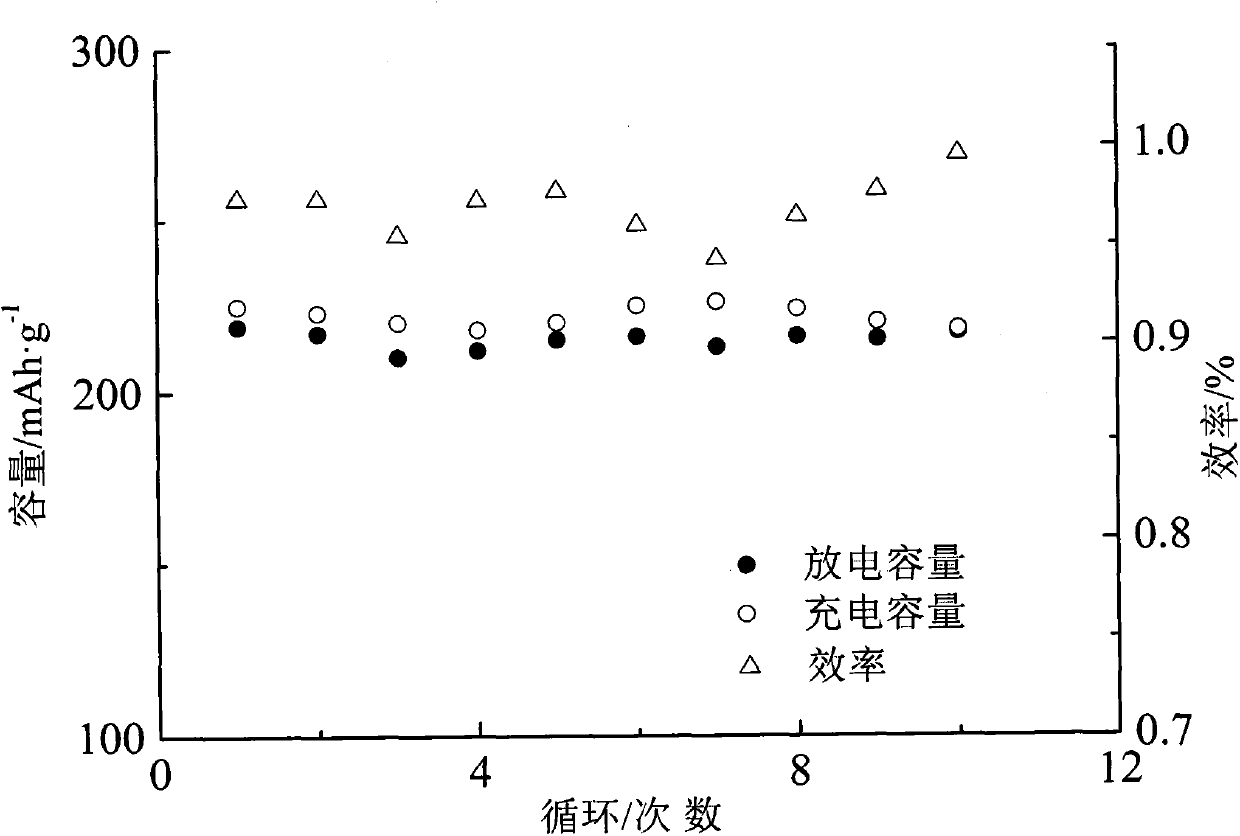

Image

  • A kind of cu2+, ce4+, ag+ doped ferric fluoride composite cathode material and preparation method

Examples


Embodiment 1

[0021] Embodiment 1: Fe(NO 3 ) 3 9H 2 O and ammonium fluoride (1.0:3.2 in molar ratio) and 3.2% by weight of Cu(C 2 o 4 )·0.5H 2 O, Ce(NH 4 ) 2 (NO 3 ) 6 , 4% by weight of AgNO 3 , 0.6% by weight of Tween-80 and 0.5% by weight of ethanol are ball milled at room temperature for 5 hours under the protection of high-purity nitrogen in a high-energy ball mill. Heat up to 450 degrees and keep the temperature for 3 hours, then cool down to prepare Cu 2+ , Ce 4+ , Ag + doped modified FeF 3 Cathode material.

Embodiment 2

[0022] Embodiment 2: FeCl 3 ·6H 2 O and ammonium fluoride (molar ratio 1.0:3.6) and 6.5% by weight of Cu(C 2 o 4 )·0.5H 2 O, the weight percent is 13% Ce (NH 4 ) 2 (NO 3 ) 6 , 8% by weight of AgNO 3 , Span-60 with a weight percentage of 0.9% and ethanol with a weight percentage of 1.0% were ball milled at room temperature for 20 hours under the protection of high-purity nitrogen in a high-energy ball mill, and then the materials were taken out, and the temperature was raised under the protection of a mixed gas of 5% hydrogen and 95% argon After cooling to 400 degrees for 6.5 hours, the preparation of Cu 2+ , Ce 4+ , Ag + doped modified FeF 3 Cathode material.

Embodiment 3

[0023] Embodiment 3: Fe 2 (SO 4 ) 3 9H 2 O and ammonium fluoride (molar ratio 1.0:3.5) and 15% by weight of Cu(NO 3 ) 2 ·3H 2 O, the weight percent is 7.5% Ce(NH 4 ) 2 (NO 3 ) 6 , 13% by weight of AgNO 3 1.5% by weight of Tween-80 and 2.0% by weight of ethanol were ball milled at room temperature for 10 hours under the protection of high-purity argon in a high-energy ball mill, and then the materials were taken out and protected by a mixed gas of 5% hydrogen and 95% argon. Heat up to 350 degrees and keep the temperature for 8.5 hours, then cool down to prepare Cu2 + , Ce 4+ , Ag + doped modified FeF 3 Cathode material.


PUM


Abstract

The invention relates to a Cu<2+>, Ce<4+>, Ag<+> doping modified iron fluoride positive pole material and a preparation method thereof. The method comprises the following step: performing ball milling on copper salt, cerium salt, silver salt and synthesis raw materials in a high-energy ball mill for a certain time, and performing heat treatment to obtain the FeF3 positive pole material. The Cu<2+> partially occupies iron ions of FeF3 for coordination, thereby being beneficial to increase the discharge potential and improve the energy density; the high-valence Ce<4+> is doped, thereby being beneficial to increase the specific capacity of the material; and the Ag<2+> is doped, thereby reducing the conversion reaction activation energy during charge. Thus, the invention is beneficial to improve the rate characteristic and energy density, thereby improving the comprehensive electrochemical property of the material.

Description

technical field [0001] The invention relates to the technical field of a method for manufacturing a high-capacity iron fluoride composite lithium battery cathode material. Background technique [0002] Lithium-ion secondary batteries have the absolute advantages of high volume, weight-to-energy ratio, high voltage, low self-discharge rate, no memory effect, long cycle life, and high power density. Currently, the global mobile power market has an annual share of more than 30 billion US dollars and Gradually grow at a rate of more than 10%. Especially in recent years, with the gradual depletion of fossil energy, new energy sources such as solar energy, wind energy, and biomass energy have gradually become alternatives to traditional energy sources. Among them, wind energy and solar energy are intermittent, and a large amount of energy is used simultaneously to meet the needs of continuous power supply. Energy storage batteries; urban air quality problems caused by automobile ...

Claims


Application Information

Patent Timeline
Patent Type & Authority Patents(China)
IPC IPC(8): C01G49/10H01M4/58H01M4/62
CPCY02E60/10
Inventor 徐玲霞水淼徐晓萍陈姝郑卫东高珊舒杰冯琳任元龙
Owner 山东格新精工有限公司
Learn More