Gear adjusting type injection allocation device for polymer injection well

A technology of dispenser and polymer injection well, which is applied in wellbore/well components, production fluids, earth-moving drilling and other directions, can solve the problems of easy blockage of the outlet, inconvenient adjustment of polymer injection amount, complex structure, etc. The effect of convenient flow adjustment, simple structure and flexible operation

Active Publication Date: 2014-11-19
HARBIN INST OF TECH
View PDF6 Cites 7 Cited by
  • Summary
  • Abstract
  • Description
  • Claims
  • Application Information

AI Technical Summary

Problems solved by technology

[0003] The purpose of the present invention is to solve the problems of complex structure, inconvenient adjustment of polymer injection volume and easy blockage of the outlet in the existing polymer dispenser

Method used


Image

  • Gear adjusting type injection allocation device for polymer injection well
  • Gear adjusting type injection allocation device for polymer injection well
  • Gear adjusting type injection allocation device for polymer injection well

Examples


specific Embodiment approach 1

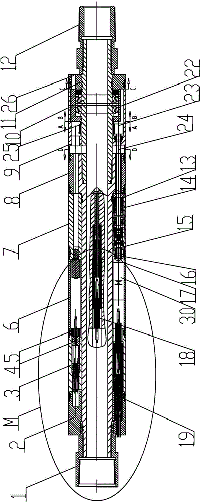
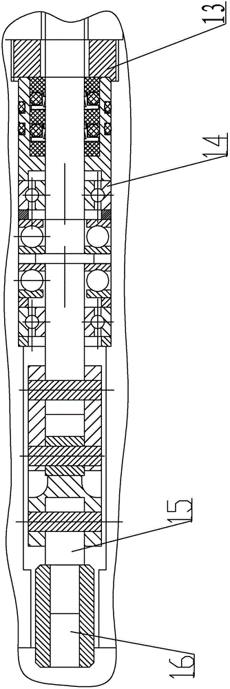
[0010] Specific implementation mode one: combine Figure 1-Figure 7 Describe this embodiment, a gear-adjustable dispenser for polymer injection wells in this embodiment includes an upper joint body 1, an upper cable body 2, a pin body 3, a motor housing 6, a bearing housing 7, and a connecting body 8. Upper outer casing 9, central tube 10, lower outer casing 11, lower joint body 12, motor 30, pinion gear 23, pinion gear shaft 24 and bull gear 25, and the outer surface of the connecting body 8 is installed sequentially from top to bottom There are upper joint body 1, upper cable body 2, pin body 3, motor housing 6 and bearing housing 7, connecting body 8 and upper joint body 1 are connected by thread, and the outer surface of central tube 10 is from top to bottom. The upper outer casing 9, the lower outer casing 11 and the lower joint body 12 are installed in sequence, the central pipe 10 and the lower joint body 12 are connected by thread, the connecting body 8 and the central...

specific Embodiment approach 2

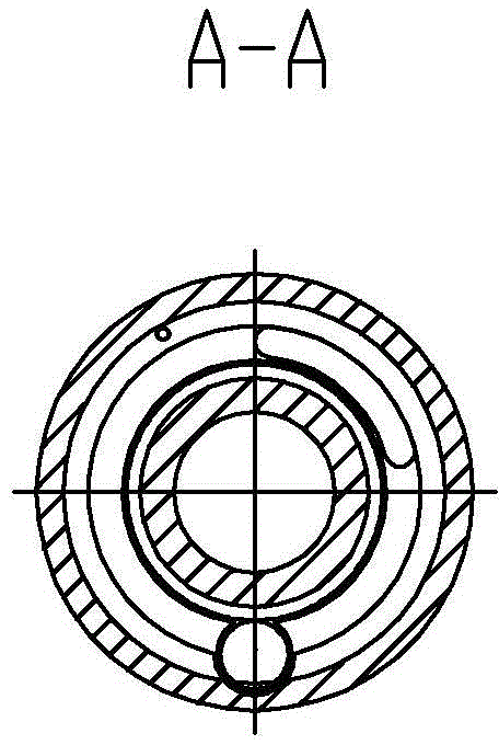
[0012] Specific implementation mode two: combination Figure 4 To describe this embodiment, the central angle of the sector block 22-1 in this embodiment is 75°-90°. Such setting is convenient for adjusting polymers with different flow rates. Other compositions and connections are the same as in the first embodiment.

specific Embodiment approach 3

[0013] Specific implementation mode three: combination Figure 4 To describe this embodiment, the central angle of the sector block 22 - 1 in this embodiment is 78°, 80°, 82°, 85° or 90°. In this way, the flow adjustment and the adjustment inlet 26 cooperate with each other at this time, and the state of the flow adjustment is the best. Other compositions and connections are the same as those in Embodiment 1 or Embodiment 2.


PUM


Abstract

The invention relates to an injection allocation device, in particular to a gear adjusting type injection allocation device for a polymer injection well. The problems that the structure of an existing polymer injection allocation device is complex, the polymer injection amount is inconvenient to adjust, and an outlet is prone to being blocked are solved. An upper connector body, an upper cable body, an contact pin body, a motor shell body and a bearing shell body are sequentially arranged on the outer surface of a connecting body of the device from top to bottom, the connecting body and the upper connector body are connected through threads, an upper outer shell body, a lower outer shell body and a lower connector body are sequentially arranged on the outer surface of a central tube from top to bottom, the central tube is connected with the lower connector body through threads, the connecting body is connected with the central tube through threads, a motor is arranged in the motor shell body, the central tube is sleeved with a large gear, one end of a small gear shaft is connected with the motor, the other end of the small gear shaft is sleeved with a small gear, the large gear is meshed with the small gear, and the central tube is sleeved with a blocking sheet. The gear adjusting type injection allocation device is used for oil exploitation.

Description

technical field [0001] The invention relates to a lower gear-regulated polymer driving device, in particular to a gear-regulated injector for polymer injection wells, which belongs to the field of petroleum exploitation. Background technique [0002] With the continuous development of oilfield development, polymer flooding technology has gradually replaced the original water flooding oil flooding. Due to the complex downhole environment and the high viscosity of the polymer, the current manual fishing technology cannot achieve flow monitoring and accurate flow injection. At the same time, the construction is very difficult and cannot meet the requirements of polymer injection. Therefore, it is decided to develop polymer injection well monitoring and adjustment. system to improve the oil displacement effect. At present, the commonly used spool-adjustable dispenser has a small outlet area, is easy to block, and is inconvenient to adjust, and is difficult to start under high-l...

Claims


Application Information

Patent Timeline
Patent Type & Authority Applications(China)
IPC IPC(8): E21B43/22
Inventor 李隆球周德开张广玉宋文平刘伟民康鹏
Owner HARBIN INST OF TECH
Why Eureka
Try Eureka