
Submersible pump

A submersible pump and pump casing technology, applied in the field of liquid pumps, can solve problems such as insufficient efficiency research, and achieve the effects of enhanced water drawing efficiency, high working efficiency, and increased contact area

Inactive Publication Date: 2014-11-19
苏州通力电气有限公司
View PDF5 Cites 1 Cited by
  • Summary
  • Abstract
  • Description
  • Claims
  • Application Information

AI Technical Summary

Problems solved by technology

The current submersible pump impellers are the same, and there is insufficient research on how to improve the impeller to improve the efficiency of submersible pumps

Method used


Image

  • Submersible pump
  • Submersible pump

Examples


Embodiment

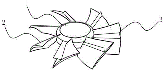
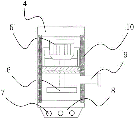
[0015] A kind of submersible pump of the present embodiment comprises a pump casing 4, a motor 5, an impeller 6, a water outlet 9 and a base 8, the outer wall of the base 8 is provided with a water inlet 7 and is fixed on the lower end of the pump casing 4, the impeller 6 and the motor 5 The shaft of the shaft is fixedly connected by a pin key, the impeller 6 is arranged near the base 8, and the water outlet 9 is arranged on the side wall of the pump casing 4. The impeller 6 includes a hub 1 and seven blades 2 arranged around the periphery of the hub. The blades 2 are detachably installed on the hub 1. The blades 2 are curved structures. Each blade 2 is provided with a convex surface 3, and the convex surface 2 is connected to the blade of the blade. The angle between the surfaces is 60 degrees, and one end of the convex surface 3 is close to the hub 1 and radiates outward along the extending direction of the blades 2 . A water seal is provided between the base 8 and the motor...


PUM


Abstract

The invention relates to a submersible pump, and belongs to the technical field of liquid pumps. The efficient submersible pump comprises a pump shell, a motor, an impeller, a water outlet and a base. A water inlet hole is formed in the base which is fixed at the lower end of the pump shell, the impeller is fixedly connected with a shaft of the motor, the impeller is close to the base, and the water outlet is formed in the side wall of the pump shell. The impeller comprises a hub and at least three blades arranged around the periphery of the hub, protruding faces are arranged on the blades, and one ends of the protruding faces are close to the hub and are outwards radiate in the extension directions of the blades. The efficient submersible pump is higher in water drawing efficiency and work efficiency, and quieter in work.

Description

technical field [0001] The invention relates to a submersible pump and belongs to the technical field of liquid pumps. Background technique [0002] Submersible pump is an important equipment for deep well water extraction. When in use, the whole unit dives into the water to work. Before starting the pump, the suction pipe and the pump must be filled with liquid. After the pump is turned on, the impeller rotates at a high speed, and the liquid in it rotates with the blades. Under the action of centrifugal force, it flies away from the impeller and shoots out. The speed of the injected liquid gradually slows down in the diffusion chamber of the pump casing, and the pressure gradually increases. Outlet, the discharge pipe flows out. At this time, a vacuum low-pressure area without air and liquid is formed at the center of the blade due to the liquid being thrown to the surroundings. The liquid in the liquid pool flows into the pump through the suction pipe under the action ...

Claims


Application Information

Patent Timeline
Patent Type & Authority Applications(China)
IPC IPC(8): F04D29/22F04D29/24F04D29/42F04D29/66
Inventor 叶爱琴陆俊芳张薇华
Owner 苏州通力电气有限公司
Learn More