Safety double-sealed ball valve

A double-sealing, ball valve technology, applied in valve details, valve device, valve shell structure and other directions, can solve the problems of high-risk chemical product leakage, valve body burst, pressure can not be discharged, etc., to achieve compact and simple structure, reliable bilateral sealing, Simple opening and closing operation

Inactive Publication Date: 2014-11-19
洪元生
View PDF5 Cites 3 Cited by
  • Summary
  • Abstract
  • Description
  • Claims
  • Application Information

AI Technical Summary

Problems solved by technology

When the traditional floating ball valve is in the closed state, if the medium in the cavity of the ball will increase abnormally, for example, some media will increase the pressure abnormally when the temperature rises. Because the cavity is sealed, the pressure cannot be discharged. When the pressure is higher than the valve body can bear pressure range, it will produce a burst or explosion
[0004] The existing floating ball valve can only achieve sealing, and cannot discharge pressure to achieve safety protection under the condition of abnormal pressure increase. If the existing ball valve is used under the condition of abnormal pressure increase, there will be safety hazards
[0005] The perforated pressure relief ball valve used under special working conditions, such as high-risk chemical industry, the valve body may increase the pressure abnormally under these working conditions. If there is no pressure relief function during abnormal pressure increase, the valve body will burst, causing high-risk chemical industry A large amount of product leakage, the upstream of the valve body of the existing perforated pressure relief ball valve is connected with a hole in the middle cavity of the valve body, which avoids the bursting of the valve body caused by the pressure of the middle cavity when the pressure is abnormally increased, but only the downstream end of this ball valve is sealed. Cannot achieve double seal

Method used


Image

  • Safety double-sealed ball valve
  • Safety double-sealed ball valve
  • Safety double-sealed ball valve

Examples


Embodiment 1

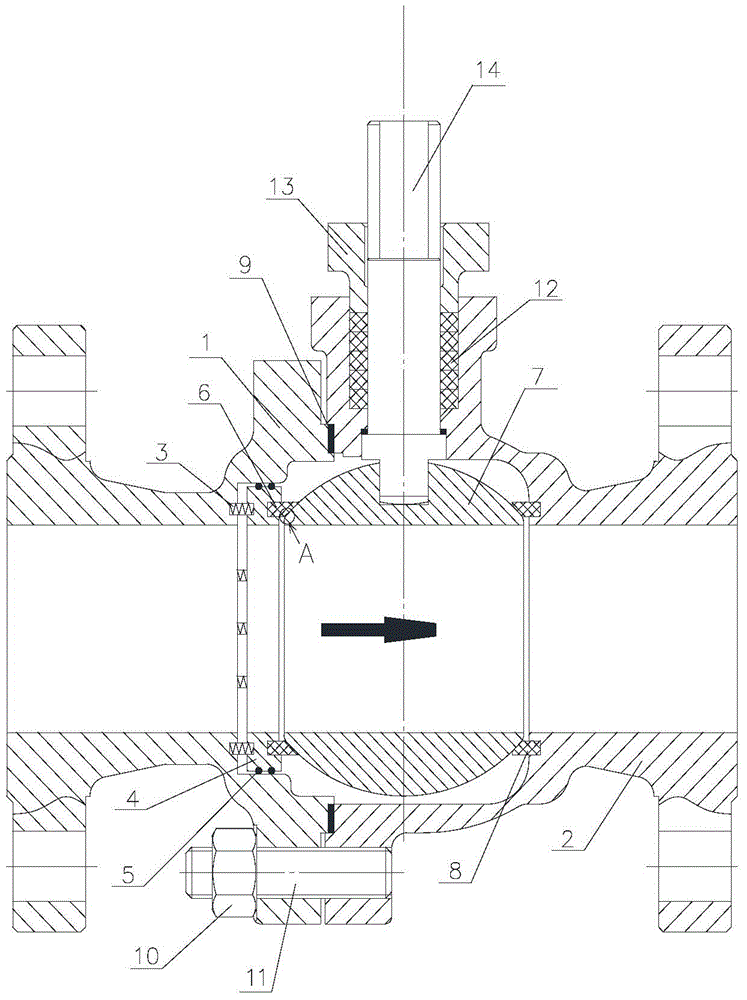
[0060] Such as figure 1 A kind of floating ball valve of the present invention shown comprises valve body, sphere (7) and switch body, and valve body comprises the inlet valve body (1) and the outlet at both ends of the sphere (7) whose axial direction is perpendicular to the axial direction of switch body (7). The valve body (2), the gasket (9) perpendicular to the axial direction of the valve body is arranged between the inlet valve body (1) and the outlet valve body (2), and the sealing device is arranged between the valve body and the ball (7). It includes a spring, an annular support ring, a valve seat and an O-ring arranged in the groove of the outer wall of the annular support ring in sequence along the axial direction of the valve body. The switch body is embedded in the outlet valve body (2), and the switch body axially It is perpendicular to the axial direction of the valve body and passes through the center of the ball (12). The inlet valve body (1) and the outlet ...

Embodiment 2

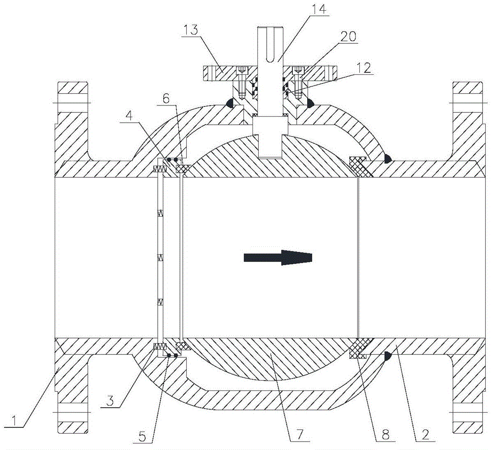
[0077] As shown in 1, a floating ball valve of the present invention includes a valve body, a ball (7) and a switch body, and the valve body includes an inlet valve body (1) at the upstream and downstream ends of the ball (7) whose axial direction is perpendicular to the axial direction of the switch body and the outlet valve body (2), a gasket (9) perpendicular to the axial direction of the valve body is provided between the inlet valve body (1) and the outlet valve body (2), and a sealing device is provided between the valve body and the sphere (7). The sealing device includes a spring arranged in sequence on the axial direction of the valve body, an annular support ring, a valve seat and an O-shaped sealing ring arranged in the groove of the outer wall of the annular support ring. The switch body is embedded in the outlet valve body (2), and the switch body axis The direction is perpendicular to the axial direction of the valve body and passes through the center of the ball ...

Embodiment 3

[0094] Such as figure 1 As shown, a kind of floating ball valve of the present invention comprises valve body, sphere (7) and switch body, and valve body comprises the inlet valve body (1) and the inlet valve body (1) and The outlet valve body (2), the gasket (9) perpendicular to the axial direction of the valve body is arranged between the inlet valve body (1) and the outlet valve body (2), and the sealing device is arranged between the valve body and the sphere (7). The device includes springs arranged in sequence on the axial direction of the valve body, an annular support ring, a valve seat and an O-shaped sealing ring arranged in the groove of the outer wall of the annular support ring. The switch body is embedded in the outlet valve body (2), and the switch body axially It is perpendicular to the axial direction of the valve body and passes through the center of the ball (12).

[0095] The inlet valve body (1) and the outlet valve body (2) are bolted.

[0096] The swit...


PUM


Abstract

The invention provides a safety double-sealed ball valve which comprises a valve body, a ball body (7) and a switch body. The valve body comprises an inlet valve body (1) and an outlet valve body (2) which are located at the upstream end and the downstream end of the ball body (7), the axial direction of the inlet valve body (1) and the axial direction of the outlet valve body (2) are perpendicular to the axial direction of the switch body, a gasket (9) perpendicular to the axial direction of the valve body is arranged between the inlet valve body (1) and the outlet valve body (2), a sealing device is arranged between the valve body and the ball body (7) and comprises a spring, an annular supporting ring, a valve seat and an O-shaped sealing ring, the spring, the annular supporting ring and the valve seat are sequentially arranged in the axial direction of the valve body, the O-shaped sealing ring is arranged in a groove in the outer wall of the annular supporting ring, the switch body is embedded in the outlet valve body (2), the axial direction of the switch body is perpendicular to the axial direction of the valve body, and the switch body penetrates through the center of the ball body (7). Under the condition that pressure rises in a cavity in the valve body abnormally, the ball valve can discharge pressure rapidly from an upstream or downstream pipeline, and safety protection is achieved.

Description

technical field [0001] The invention relates to a valve, in particular to a safety double-seal ball valve. Background technique [0002] The ball valve was born in the 1950s. With the rapid development of science and technology, the continuous improvement of production technology and product structure, ball valves are widely used in petroleum refining, long-distance pipelines, chemical industry, papermaking, pharmaceuticals, water conservancy, electric power, municipal , steel and other industries occupy a pivotal position in the national economy. It has an opening and closing part driven by the valve stem. The opening and closing part is a sphere with a circular through hole or channel passing through its axis. The ball valve is mainly used to cut off, distribute and change the flow direction of the medium in the pipeline. It only needs to be rotated 90 degrees and a small rotational torque can be closed tightly. Ball valves are most suitable for on-off and shut-off valve...

Claims


Application Information

Patent Timeline
Patent Type & Authority Applications(China)
IPC IPC(8): F16K5/06F16K5/20F16K27/06
CPCF16K5/0689F16K5/08F16K5/201
Inventor 洪元生
Owner 洪元生
Why Eureka
Try Eureka