
OPGW DC ice-melting system

A DC ice melting and ice melting technology, applied in instruments, thermometers, electrical components, etc., can solve the problems that are not mentioned, and achieve the effect of improving the level of intelligence, realizing automatic dynamic control, and strengthening practical application value.

Active Publication Date: 2015-12-02
CHINA ELECTRIC POWER RES INST +2
View PDF4 Cites 12 Cited by
  • Summary
  • Abstract
  • Description
  • Claims
  • Application Information

AI Technical Summary

Problems solved by technology

The invention patent with the application number 200910175452.2 discloses a distributed optical fiber temperature measurement system, including a single-chip microcomputer control board, an optical fiber temperature field information acquisition module, a photoelectric detector and a circuit signal post-processing module, which can complete the temperature monitoring of the temperature measurement optical cable. There is no mention of the application on the OPGW optical cable to solve the temperature over-limit alarm and the control function of the deicing progress during the ice melting process

Method used


Image

  • OPGW DC ice-melting system
  • OPGW DC ice-melting system
  • OPGW DC ice-melting system

Examples


Embodiment Construction

[0036] The present invention will be described in further detail below in conjunction with the accompanying drawings.

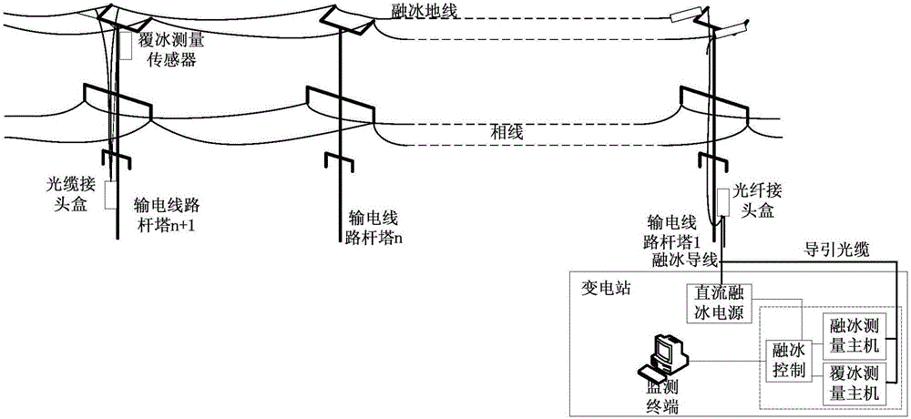
[0037]According to the current monitoring technology level and line engineering construction requirements, the ice melting measurement host and ice coating measurement host are installed in the computer room of the substation. After the ice coating measurement signal is generated, it is sent from the substation host and transmitted to each ice coating monitoring point of the transmission line. After modulation, it is sent back to the grating demodulation host to analyze the ice thickness data; after the ice melting measurement optical signal is also sent from the host of the substation, it carries the temperature information of the optical cable distribution and returns to the demodulation host of the substation, and the temperature of the optical cable is obtained after analysis data. Through the background monitoring software for data analysis, master the i...


PUM


Abstract

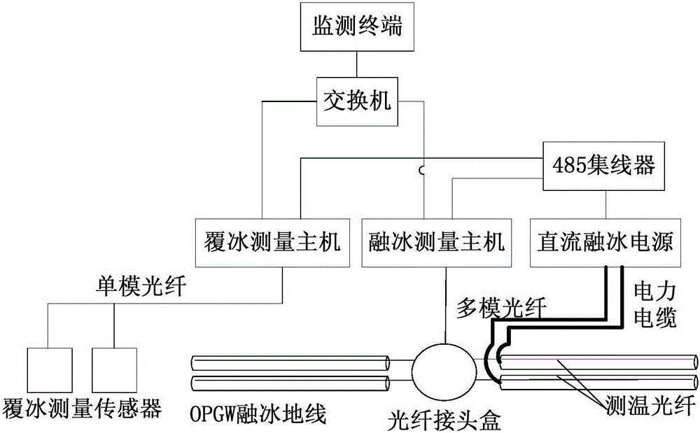
The invention discloses an OPGW DC ice-melting system, and the system comprises an ice-melting ground line, an ice covering measurement sensor, an ice covering measurement host, an ice-melting measurement host, a DC ice-melting power supply, a 485 concentrator, a switcher, a monitoring terminal, and an optical cable joint box. The ice-melting ground line is connected with the ice covering measurement host through the optical cable joint box, and the ice covering measurement sensor is connected with the ice covering measurement host through a single-mode optical fiber. The ice covering measurement host, the ice-melting measurement host and the DC ice-melting power supply are respectively connected with the 485 concentrator. The ice covering measurement host and the ice-melting measurement host are connected with the monitoring terminal through the switcher. The system achieves the overtemperature monitoring in a long-distance circuit ice melting process and circuit ice melting control under the different conditions in a deicing period through employing the technology of distributed optical temperature measurement and the technology of on-line analysis. The system achieves the ice covering monitoring of a power transmission rod tower under the on-site passive conditions, electromagnetic radiation resistance conditions and severe monitoring conditions through employing the technology of optical fiber grating ice covering measurement, and has a higher practical value.

Description

technical field [0001] The invention relates to a direct current ice melting system, in particular to an OPGW direct current ice melting system based on distributed optical fiber temperature measurement and fiber grating ice thickness measurement. Background technique [0002] The ground wire of the overhead transmission line is used for lightning protection in the transmission line. OPGW (OPGW) has the functions of communication channel and lightning protection wire, and has been widely used in high-voltage transmission lines for more than ten years. In terms of grounding methods, at present, ordinary lightning conductors in engineering mostly adopt the method of section insulation and one-point grounding; while OPGW basically adopts the method of base-by-base grounding. Due to the fact that the ground wire and the iron tower are not insulated under normal circumstances, the previous DC deicing scheme for transmission conductors cannot be directly applied to the icing of t...

Claims


Application Information

Patent Timeline
IPC IPC(8): H02G7/16G01K11/32G01B11/02G02B6/44
Inventor 雷煜卿陈希张晔汪洋
Owner CHINA ELECTRIC POWER RES INST
Learn More