A flue gas treatment device

A technology for flue gas treatment and flue, which is applied in the direction of lighting and heating equipment, and can solve the problems of large maintenance, high energy consumption, and failure to achieve expected results.

Active Publication Date: 2018-07-03
北京大学包头创新研究院
View PDF8 Cites 0 Cited by
  • Summary
  • Abstract
  • Description
  • Claims
  • Application Information

AI Technical Summary

Problems solved by technology

However, there are many problems, such as failure to achieve expected results, high energy consumption, unstable operation, and large post-maintenance, etc.

Method used


Image

  • A flue gas treatment device
  • A flue gas treatment device
  • A flue gas treatment device

Examples


Embodiment 1

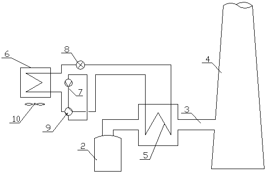
[0026] Such as figure 1 As shown, the flue gas treatment device 1 in the dotted line box, the device 1 includes a vapor compression cycle system, that is figure 1 The compressor 7, the first heat exchanger 5, the throttling member 8 and the second heat exchanger 6 are sequentially connected by the refrigerant pipeline, and the refrigerant passes through the first heat exchanger 5 and throttling according to the direction of the outlet of the compressor 7. After components 8 and second heat exchanger 6, return to compressor 7. That is, the refrigerant inlet of the first heat exchanger 5 is connected to the compressor 7 , the refrigerant outlet is connected to the throttling component 8 , and the second heat exchanger 6 is also connected between the compressor 7 and the throttling component 8 .

[0027] Specifically, the first heat exchanger 5 is arranged in the flue 3 between the wet desulfurization device 2 and the chimney 4, and the first heat exchanger 5 is used as a conden...

Embodiment 2

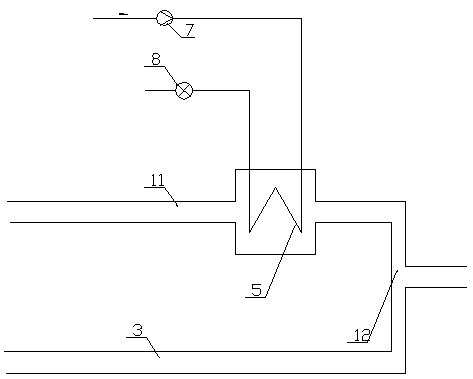
[0031] figure 2 The difference from Embodiment 1 is that the first heat exchanger 5 is arranged in the bypass flue 11 to exchange heat with the flue gas in the bypass flue 11, and a part of the flue gas passes through the bypass flue. After the first heat exchanger 5 in the channel 11 performs heat exchange, the treated flue gas is mixed with another part of the flue gas at the junction 12 to form flue gas whose temperature is higher than the minimum non-condensing temperature T.

[0032] In the actual flue gas treatment, custom-made heat treatment devices are often used. In order to meet the design requirements of the flue gas treatment device, only part of the flue gas will be processed and then mixed, which improves the flexibility of the flue gas treatment device. sex. For another example, when the equipment in another flue is overhauled, the heat exchanger in the bypass flue can take on the job of heating the flue gas.

Embodiment 3

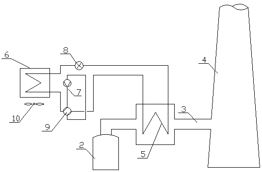
[0034] Such as image 3 As shown, the difference between this embodiment and Embodiment 1 is that a four-way valve 9 is also provided in the vapor compression cycle system, and the four-way valve 9 controls the flow direction of the refrigerant in the first heat exchanger. When the four-way valve 9 is as image 3 When the flow direction in the flow is flowing, the first heat exchanger 5 is used as a condenser, that is, the flue gas treatment device includes the first heat exchanger as the first state of the condenser; when the four-way valve 9 is as Figure 4 When the flow direction in the flow direction flows, the first heat exchanger 5 is used as an evaporator, that is, the flue gas treatment device includes the first heat exchanger as the second state of the evaporator.

[0035] In this embodiment, the function of the second heat exchanger will also change correspondingly with the switching of the four-way valve 9. In the first state, the second heat exchanger 6 is used as ...


PUM


Abstract

A flue gas treatment device, especially a device for treating flue gas after a wet flue gas desulfurization process. Specifically, a flue gas treatment device is characterized in that the flue gas treatment device is a vapor compression cycle system including a first heat exchanger, and the first heat exchanger is arranged between the wet desulfurization device and the chimney In the flue between; the first heat exchanger is used as the condenser of the vapor compression cycle system to heat the flue gas. The invention increases the lifting height of the flue gas at the chimney outlet, avoids condensation, prevents the occurrence of gypsum rain, and protects the environment well; reduces the corrosion of the chimney; reduces the operating load of the cooling tower and the power generation efficiency of the unit also improved.

Description

technical field [0001] The invention relates to a flue gas treatment device, in particular to a device for treating flue gas after a wet flue gas desulfurization process. Background technique [0002] Currently, most power plants have installed flue gas desulfurization systems. The use of wet flue gas desulfurization technology, such as limestone-gypsum desulfurization technology, is prone to gypsum rain in the process of flue gas discharge from the chimney, that is, the "wet chimney" situation, which not only brings a certain degree to the operation safety of power plants harm, and pollute the surrounding ecological environment. Most of the current solutions use the flue gas heat exchanger (GGH), and some use the secondary air of the boiler to heat the clean flue gas, increase the electric heating device, control the flue gas flow rate, and strengthen the effect of the demister. However, there are many problems, such as failure to achieve expected results, high energy con...

Claims


Application Information

Patent Timeline
Patent Type & Authority Patents(China)
IPC IPC(8): F23J15/08
Inventor 张信荣李宁崔增光杜洪亮付加庭刘勇王少茹刘彪于华伟李林凤
Owner 北京大学包头创新研究院
Why Eureka
Try Eureka