
Household electrical appliance monitoring system based on ZigBee

A household appliance and monitoring system technology, applied in the field of electronic information, can solve the problems of poor system scalability, high cost, cumbersome management system wiring, etc., to achieve reasonable power saving, low power consumption, and good scalability Effect

Inactive Publication Date: 2014-11-19
长沙辉云电子科技有限公司
View PDF5 Cites 2 Cited by
  • Summary
  • Abstract
  • Description
  • Claims
  • Application Information

AI Technical Summary

Problems solved by technology

The wiring of the management system constructed in this way is cumbersome, and there will be various cables that are difficult to get rid of, and the scalability of the system is also poor and the cost is high.

Method used


Image

  • Household electrical appliance monitoring system based on ZigBee
  • Household electrical appliance monitoring system based on ZigBee
  • Household electrical appliance monitoring system based on ZigBee

Examples


no. 1 example

[0013] The first embodiment: managed by the user by operating the main controller

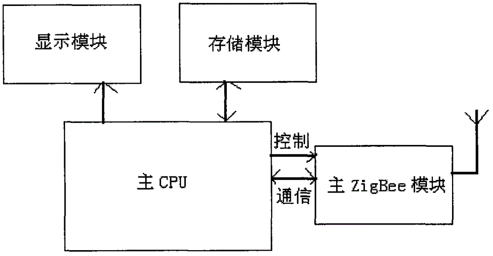
[0014] like figure 1 As shown, the household appliance monitoring system according to the present invention includes a main controller, a sub-controller and a household appliance. The main controller and the sub-controllers are connected by a bus, and the bus adopts the ZigBee wireless communication mode. ZigBee technology is a short-range, low-complexity, low-power, low-speed, low-cost two-way wireless communication technology. It is mainly used for data transmission between various electronic devices with short distance, low power consumption and low transmission rate, as well as typical applications with periodic data, intermittent data and low response time data transmission.

[0015] The main controller is used for receiving the working data of the household appliance sent by the sub-controllers and sending user control signals. The sub-controller is used for collecting the working data...

no. 2 example

[0017] Second embodiment: the user uses a mobile phone as a remote control terminal for remote management

[0018] like figure 2 As shown, the household appliance monitoring system according to the present invention includes a remote control terminal, a main controller, a sub-controller and a household appliance. The remote control terminal can be a mobile phone or other user terminal, which can perform wireless communication by means of GPRS. The main controller and the sub-controllers are connected by a bus, preferably a high-speed, full-duplex, synchronous communication bus. The bus adopts ZigBee wireless communication mode. The main controller is used for receiving the working data of the household appliance sent by the sub-controllers and sending user control signals. The sub-controller is used for collecting the working data of the household appliance and sending it to the main controller, and receiving the instruction of the main controller to execute the operation ...


PUM


Abstract

The invention provides a household electrical appliance monitoring system based on ZigBee. The system comprises a household electrical appliance, a main controller and a sub-controller. The main controller is used for receiving work data of the household electrical appliance and sending user control signals; and the sub-controller is used for acquiring the work data of the household electrical appliance, sending the data to the main controller and receiving instructions of the main controller to execute operation on the household electrical appliance. The main controller and the sub-controller are connected through a bus which employs a ZigBee wireless communication mode. According to the invention, the household electrical appliance monitoring system has the advantages of good scalability, low cost, low power consumption and the like, the overall system complexity is quite low, work conditions of the household electrical appliance can be known in real time, the electricity consumption information, the equipment states and the like of the household electrical appliance can be safely metered and monitored, and intelligent interaction is realized; and the household electrical appliance can also be remotely monitored by use of a mobile phone.

Description

technical field [0001] The invention relates to a power electronic device, in particular to a household appliance monitoring device, and belongs to the technical field of electronic information. Background technique [0002] Low-carbon economy has begun to attract attention from all walks of life. As an important part of energy consumption - household electricity, household appliances consume and use energy all the time. In recent years, with the boom of smart grid construction, the monitoring of household appliances to achieve home energy management is getting closer and closer to our lives. However, most of the home appliance monitoring systems in the prior art use wired technology, that is, various controls and communications are performed through wired wiring. The management system constructed in this way is cumbersome in wiring, and there will be the fetters of various cables that are difficult to get rid of, and the scalability of the system is also poor and the cost...

Claims


Application Information

Patent Timeline
Patent Type & Authority Applications(China)
IPC IPC(8): G05B19/418
Inventor 冯国丽何涛胡承
Owner 长沙辉云电子科技有限公司
Learn More