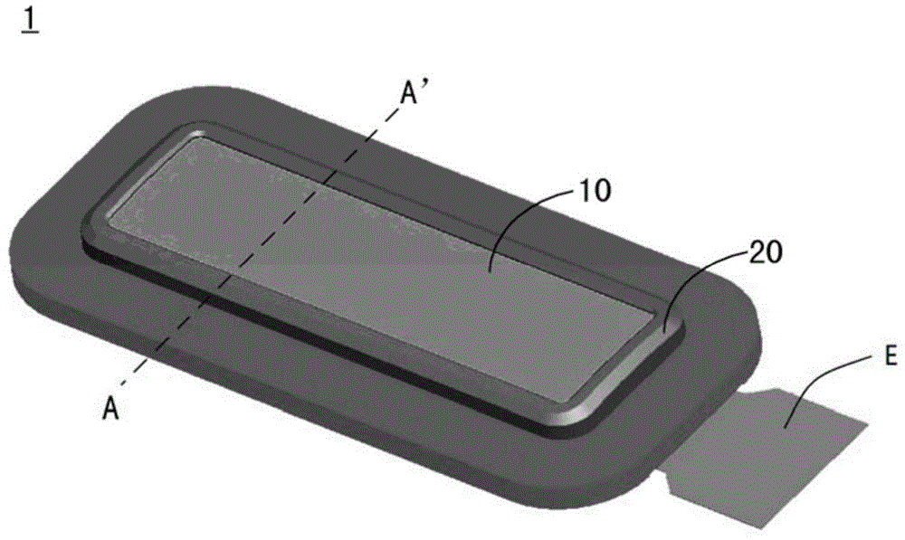
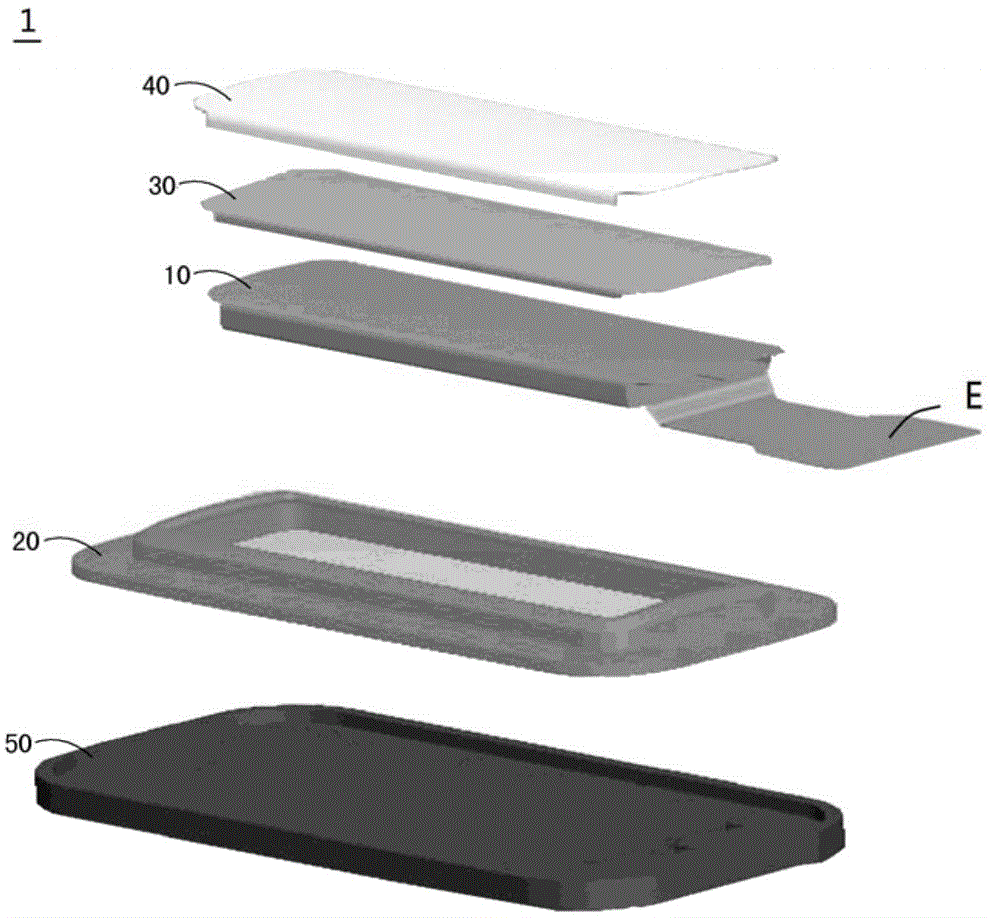
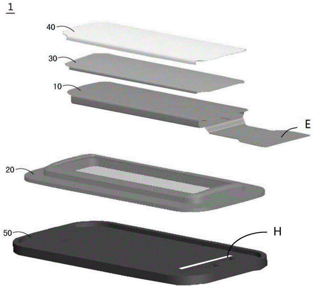
Fingerprint recognition device and terminal device
A technology of fingerprint recognition and supporting parts, which is applied in the field of biometrics, can solve the problems of increasing the difficulty of user memory, adding passwords and graphics, and conflicts between security and ease of use, so as to improve production yield and efficiency, meet the requirements of thinner, smaller structure effect
- Summary
- Abstract
- Description
- Claims
- Application Information
AI Technical Summary
Problems solved by technology
Method used
Image
Examples
Embodiment 2
[0095] The content in the second embodiment that is the same as that in the first embodiment will not be repeated here.
[0096] Figure 5 It is the fingerprint recognition module of the third embodiment of the present invention along the figure 1 The exploded schematic diagram of A-A' in the middle. Figure 5 The fingerprint recognition module 13 of the shown embodiment three and Figure 3A The difference of the fingerprint identification module 11 in the first embodiment shown is: the wrapping method between the fingerprint identification module 100 and the support 104 in the fingerprint identification module 13 , and the shape of the support 104 .
[0097] Such as Figure 5 As shown, the flexible circuit film 1000 in the fingerprint identification module 13 is shorter than the flexible circuit film 1000 in the fingerprint identification module 11, and the flexible circuit film 1000 in the fingerprint identification module 13 does not exceed the side surface of the lower ...
Embodiment 3
[0099] The content in the third embodiment is the same as that in the first embodiment, which will not be repeated here.
[0100] Figure 6 It is the fingerprint identification module of the fourth embodiment of the present invention along the figure 1 The exploded schematic diagram of A-A' in the middle. Figure 6 The fingerprint identification module 14 of the shown embodiment four and Figure 3A The difference of the fingerprint identification module 11 in the first embodiment shown is: the wrapping method between the fingerprint identification module 100 and the support 104 in the fingerprint identification module 14 , and the shape of the support 104 .
[0101] Such as Figure 6 As shown, the flexible circuit film 1000 in the fingerprint identification module 14 is shorter than the flexible circuit film 1000 in the fingerprint identification module 11, and the flexible circuit film 1000 in the fingerprint identification module 14 does not exceed the side surface of the...
Embodiment 4
[0103] The content in the fourth embodiment is the same as that in the first embodiment, which will not be repeated here.
[0104] The thickness of the protective layer 40 in the fingerprint identification device 1 of the embodiment of the present invention is, for example, 0.015 mm, the thickness of the color layer 30 is, for example, 0.01 mm, and the thickness of the adhesive between the color layer 30 and the fingerprint identification module 10 is, for example, 0.008 mm, the thickness of the flexible circuit film 1000 formed with the sensor 1002 and the control chip 1004 is, for example, 0.05 mm. Therefore, the fingerprint identification device 1 of the embodiment of the present invention can provide a very thin thickness, so as to meet the demand of terminal equipment for thinning and lightening its integrated components. The above-mentioned dimensions are for example only, and do not limit the present invention.
PUM
 Abstract
Description
Claims
Application Information
 - R&D
- Intellectual Property
- Life Sciences
- Materials
- Tech Scout
- Unparalleled Data Quality
- Higher Quality Content
- 60% Fewer Hallucinations
Browse by: Latest US Patents, China's latest patents, Technical Efficacy Thesaurus, Application Domain, Technology Topic, Popular Technical Reports.
© 2025 PatSnap. All rights reserved.Legal|Privacy policy|Modern Slavery Act Transparency Statement|Sitemap|About US| Contact US: help@patsnap.com


