750W 2-pole energy-saving and environmentally friendly motor

An energy saving, environmental protection, motor technology, applied in the field of motors, can solve problems such as low motor efficiency, and achieve the effects of reducing stator and rotor losses, reducing harmonic component losses, and reducing copper consumption

Active Publication Date: 2016-07-06
吕三元
View PDF3 Cites 0 Cited by
  • Summary
  • Abstract
  • Description
  • Claims
  • Application Information

AI Technical Summary

Problems solved by technology

[0005] The technical problem to be solved by the present invention is to provide a 750-watt 2-pole energy-saving and environmentally friendly motor with an energy efficiency level exceeding the international IE4 level in order to further save energy and improve environmental pressure in view of the generally low efficiency of electric motors at present.

Method used


Image

  • 750W 2-pole energy-saving and environmentally friendly motor
  • 750W 2-pole energy-saving and environmentally friendly motor
  • 750W 2-pole energy-saving and environmentally friendly motor

Examples


Embodiment 1

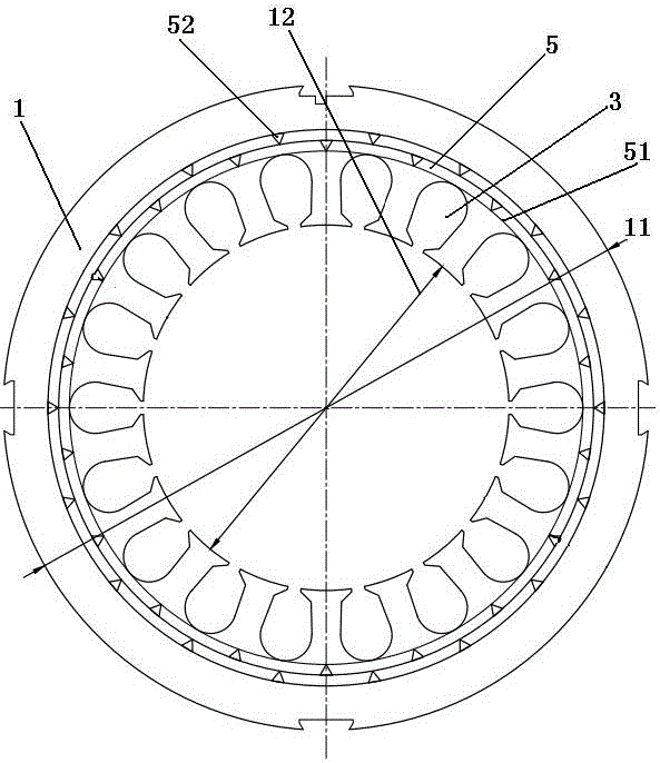
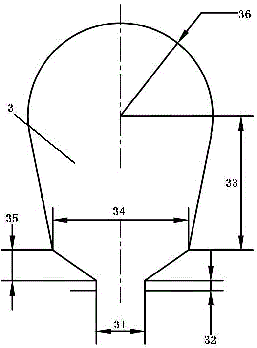
[0028] As shown in the figure, the present invention includes two core parts, the stator and the rotor. The basic material, structure and manufacturing method are the same as those of the ordinary 750-watt 2-pole three-phase asynchronous motor. The difference is that the stator outer diameter 11 of the stator core is made into 12.00cm, the stator inner diameter 12 is made into 6.80cm, and the length of the stator core is made into 10.00cm. The number of stator punching slots 3 on the stator punching plate 1 is made into 18 and distributed evenly in a ring shape, and the groove shape is made into a groove with a sloping shoulder and a round bottom, in which the slot width 31 is made 2.50mm, and the slot height 32 is made into 0.50mm, the groove top depth 33 is made into 6.90mm, the groove shoulder width 34 is made into 7.00mm, the groove shoulder height 35 is made into 1.57mm, and the groove bottom radius 36 is made into 4.78mm.

[0029] At the same time, the rotor outer diamet...

Embodiment 2

[0031]Further, on the basis of Embodiment 1, a double-layer ring-shaped stator punching hole band 5 is arranged on the periphery of the bottom of the stator punching groove 3 above the stator punching plate 1, and the inner layer of the stator punching hole band The inner ring line of ring 5 coincides with the circumscribed circumferential line 51 at the bottom of the stator punching slot. 18 evenly distributed stator punching holes 52 are arranged on the sheet hole band ring 5, and the shape of the stator punching hole 52 is set to an equilateral triangle with a side length of 2.30 mm, wherein the inner stator punching hole ring The stator punching hole 52 is located at the midpoint of the arc-shaped band between two adjacent stator punching slots, and the stator punching hole 52 on the outer stator punching hole ring is located at the inner layer stator punching hole ring. The midpoint of the arc band between the two holes of the stator punching hole 52 .

[0032] At the sa...

Embodiment 3

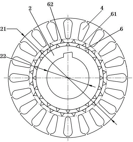
[0035] Further, the rotor punching holes 62 on the first rotor punching sheet 2 in the embodiment 2 are evenly distributed on any point of the outer rotor punching hole ring and the inner rotor punching hole ring, Then the rotor punching hole 62 on the adjacent rotor punching 2 rotates in the same direction (clockwise or counterclockwise) on the rotor punching hole ring 6 sequentially, and the displacement is 0.05mm or 0.1mm or 0.25mm or 0.35mm or a displacement of 0.5mm, when the rotor punches 2 are sequentially stacked, a spiral hole will be formed on the rotor core as a whole. When such a motor is running, it will further accelerate the heat temperature convection in the motor, and make the air flow more fully, further reduce and slow down the temperature rise, and reduce the rotor loss.


PUM


Abstract

The ultra-high-efficiency 750-watt 2-pole energy-saving and environmentally friendly motor is characterized in that the inner and outer diameters and length dimensions of the stator and rotor cores, the shape and size of the stator and rotor slots, and the number of slots have been coordinated and designed as a whole, which greatly reduces the stator and rotor. and the loss of the iron core; then add punching holes on the stator and rotor punching sheets to form iron core holes, increase heat and temperature convection in the motor, reduce and slow down the temperature rise; use special cast aluminum for the rotor to effectively improve the conductivity and heat dissipation effect; the stator The winding is tapped at half of the coil, which greatly reduces the loss of harmonic components and further reduces iron loss and copper loss. The comprehensive effect of various schemes has greatly reduced the power loss, so that the input power of this product is only 0.881kW under the premise of a stable output power of 0.75kW, and the energy conversion efficiency has reached 85.2%, which exceeds the highest level of the country's YE4 energy efficiency standard , also exceeded the highest international level IE4 grade standard, reached the international advanced level.

Description

technical field [0001] The invention relates to the technical field of electric motors, in particular to an ultra-super-high-efficiency 750-watt 2-pole energy-saving and environment-friendly electric motor exceeding the international IE4 energy efficiency standard. Background technique [0002] Electric energy is an important material energy that people rely on for survival, and its application has penetrated into various fields of society. Today's people's life and work are inseparable from electric energy. However, due to the excessive use of electric energy, it has brought huge negative effects to the natural environment in which people live, and the environmental damage is very serious. In order to improve the environment, energy conservation and emission reduction have become an unavoidable topic in the world today. In the field of electricity, because the electricity consumption of the motor system accounts for about 60% of the total electricity consumption in my count...

Claims


Application Information

Patent Timeline
Patent Type & Authority Patents(China)
IPC IPC(8): H02K17/12H02K1/16H02K1/26H02K3/28
Inventor 吕三元李桂发
Owner 吕三元
Why Eureka
Try Eureka